Continue to Site

Eng-Tips is the largest engineering community on the Internet

Intelligent Work Forums for Engineering Professionals

  • Congratulations MintJulep on being selected by the Eng-Tips community for having the most helpful posts in the forums last week. Way to Go!

Punching Shear - Transfer Slab

Status
Not open for further replies.

Babuskha Forever

Structural
Aug 20, 2023
5
Hi I have a question regarding punching shear check for transfer slab.
The transfer slab is 1.2m with a perimeter around 10m x 10m .
1) If the columns supporting the transfer slab are close to one another (lets say 1m distance c/c) Do i combine them to check punching shear? If so, do i also combine the axial force that are acting on those 2 columns?
2) As the columns supporting the transfer slab and the wall/columns comming from above are not aligned, is there any rule of thumb of the distance of column supporting the transfer slab and wall/column sitting on the transfer to minus off the column load from above.
Thank you so much for your help.
 
Replies continue below

Recommended for you

I will assume there's a good reason for two columns 1m apart instead of something like a wallumn. Just keep in mind that it's a lot of formwork.

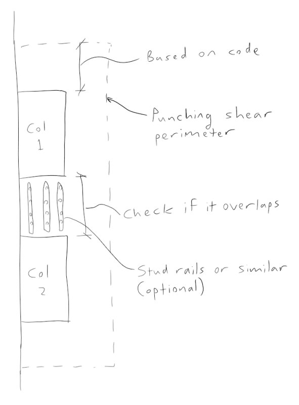
1) You should combine them for calculations if their punching shear perimeters will overlap, which I think they will. The slab will not punch around them individually. Personally, and this is my own preference, I'd add stud rails or punching shear reinforcement between the two columns to ensure that the punching shear perimeter is fully engaged on both columns. Better yet, I'd just make it a wall.

2) I generally wouldn't do that. There is no distance to me that serves that purpose. Walking columns are used for this.
 
1) If i were to combine them, the column location, do i take the centroid of the distance between the 2 columns? For the loading do i take the higher of the 2 as if i combine both of the, i am sure my shear capacity check would fail.

2) Noted!
 
punching_shear_mcai8k.png
 
You need to transform the column reactions and unbalanced moments to be at the combined punch perimeter centroid.

You absolutely should still check individual punching of the columns.

ACI allows any load inside the critical punch perimeter to act counter to the punch reaction. You will again need to transform any load above to act at the punch perimeter centroid. For large transfer reactions this can sometimes create additional unbalanced moment when acting about the punch perimeter centroid. There is a point where you get a D region and should investigate with strut-tie.
 
Perhaps not a smart way of doing it, but would it make sense when doing the individual column checks to treat a line mid-way between the columns as an edge and checking each column with 50% of the combined perimeter (i.e. not utilising any overlap)? Then also doing as Celt suggested, do a combined check for the transformed reactions.

----------------------------------------------------------------------

Why yes, I do in fact have no idea what I'm talking about
 
In order for us to provide meaningful help on this, I feel that you need to provide us with a decent sketch that indicates:

1) The proportions and locations of the columns and walls below the slab and;

2) The proportions and location of the columns and wall above the slab.

I think that this is necessary to really determine what is best and/or most efficient for a particular situation.

While it would be computationally expedient, my gut feel is that it will rarely be appropriate to just combine the loads and consider a single, faux column.

 
For the portion of the load coming into the joint via slab flexure, I would favor something in line with Eurocode provisions, as shown below. For a very thick slab, the 1.5dv may well cause the effective punching perimeters to run together. If they didn't run together, I'd be inclined to split any Mx moment into a tension and compression couple that gets resisted by the two columns separately.

Like MSL, I vote for making this a single column if possible. Or two columns with a bridging beam between them (or probably more costly for formwork). The reality of the situation is that what we know about punching shear is highly dependent on what has been tested in laboratories. And this 'aint that. I feel that going with a wall or bridge in this situation would go a long ways towards making this a more predictable condition.
 
KootK said:
Or two columns with a bridging beam between them (or probably more costly for formwork).

At 1200 thick an 1000 c/c, there's no reason that beam couldn't just be envisioned to be within the thickness of the slab.

Another approach that I like for weird situations in big transfer slabs is to just install stirrups at the column group to form a beam end of sorts that can move all of the load into the columns that need to get there. At 1200 thick, there's plenty of space for such reinforcing.

01_qktpk2.png
 
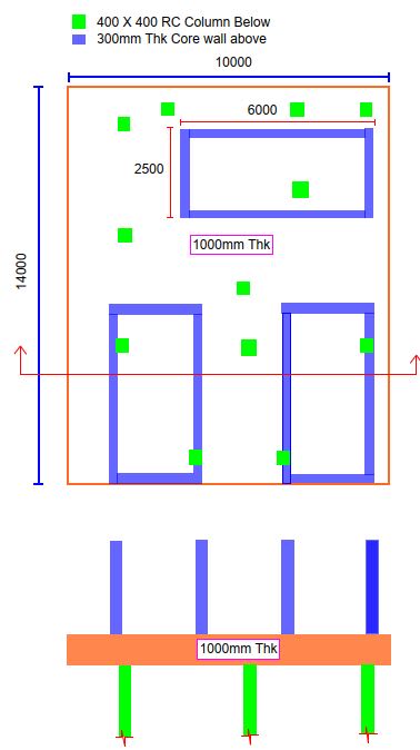
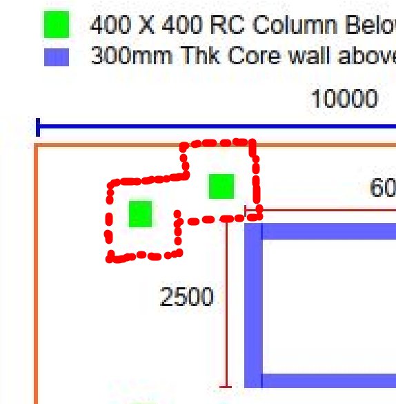
Hello! I've attached a proper sketch with proper dimensions. Would like to hear your opinion. I really want to know your opinion on overlapping punch shear perimeters too.

Capture_litpim.jpg
on.
 
OP said:
I really want to know your opinion on overlapping punch shear perimeters too.

So which columns are you considering to treat using overlapping perimeters? The two at the top left?
 
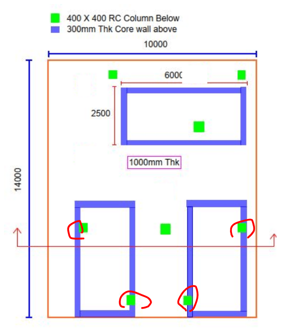
It will be very difficult model something like this with much accuracy. I'd be inclined to run multiple, simpler models to try and produce a safe result. One of those models would be as shown below. This becomes something that would behave predictably enough that you could have some confidence in the safety of the result. The three columns circled in red would, of course be bearing conditions with respect to the load coming in from the shafts.

01_jtjdnn.png
 
OP said:
the two top left and two top right

Neither groups are anywhere near close enough together that there would be value in treating them as combined in my opinion.

Surely, in the sketch below, it will be the right column doing the lion's share of the work??

01_y6osfw.png
 
Could you elaborate further meaning of producing simpler models?
Also, would it be possible for me to minus off the load cming from the shaft if the shaft is within the 2d punching critical perimeter of the column.
For the 2 columns on the right, i did an individual check however when it comes to detailing, thats where my problems starts as the shear links required extends all the way towards the second column.
 
OP said:
Could you elaborate further meaning of producing simpler models?

I drew the model for you in my previous post. What more are you looking for?

OP said:
Also, would it be possible for me to minus off the load cming from the shaft if the shaft is within the 2d punching critical perimeter of the column.

- In my mind, it seem inconsistent to use 2d for that when we assume a much shorter distance for the punching shear perimeter.

- For larger, concentrated loads, one ought to also consider the potential for shear cracking planes steeper than 45 degrees.

- I'm a lot more comfortable with such a method if STM is used to deal with it.

OP said:
For the 2 columns on the right, i did an individual check however when it comes to detailing, thats where my problems starts as the shear links required extends all the way towards the second column.

Run the stud between columns as MSL proposed. A new column along your shear path is, effectively, the best of all possible stirrup replacements, right?
 
I agree with Kootk, design for a simpler safer situation. Closer column should take all the punching load.
 
**** Thread Hijack ****

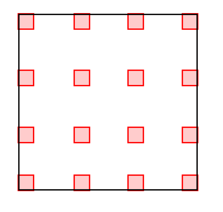
This idea has me thinking - what would happen (hypothetically) if you had an entire slab where the column grid was close enough relative to the slab depth where all of the columns have overlapping punching shear perimeters? Shear reinforcing between all of the columns to ensure they work together, like described previously - essentially create beams between the columns (to resolve a more one-way shear type of demand)? Will punching shear still occur - at some tighter section with higher capacity? Not sure what to think (or if it is worth the time to think on)

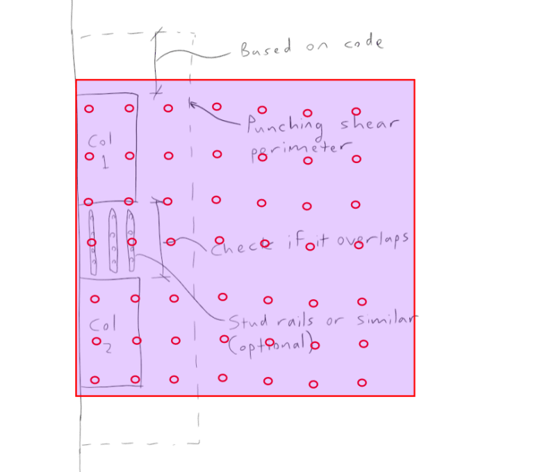
(Sample Image for sketching)
sample_u1ww7f.png


****Hijack ended****
 
With some bottom steel, I imagine that you'd mobilize a monstrous, tied arch mechanism for shear resistance.
 
Yes by that stage it's strutting directly to the columns.
 
Status
Not open for further replies.

Part and Inventory Search

Sponsor