Eng-Tips is the largest engineering community on the Internet

Intelligent Work Forums for Engineering Professionals

  • Congratulations waross on being selected by the Tek-Tips community for having the most helpful posts in the forums last week. Way to Go!

Purlin design: Failing under slenderness ratio 3

Status
Not open for further replies.

hamy08

Materials
Feb 24, 2017
33
0
0
PK
I am analyzing shed design on staad pro. I have released moments at the start and end of roof purlins. But still purlins are failing under slenderness. May be because the force is acting at the ends and the purlins are behaving like columns. Which is also true in real case as the purlins are supported between the rafters with bolts at the web of purlin and at upper flange of rafter beam.
Can any one explain me which type of end supports should be considered for purlins?
why it is failing under slenderness, however it should act like a beam?
Can we still use purlins even failing under slenderness ration?
 
 https://files.engineering.com/getfile.aspx?folder=d3af0809-db0f-478a-a48b-c24415b9db69&file=purlins.jpg
Replies continue below

Recommended for you

Whether as beams or as struts, purlin sections need to be braced laterally. You show some rods, but I don't know if your program recognizes a benefit from the rods. Perhaps a more robust bridging system would overcome the slenderness problem.
 
The roofing does brace the top flange, if direct screwed. But the bottom flange remains unbraced. But the most critical bracing condition is during construction. Don't try to walk on unbraced purlins.
 
hokie66 : Can you share with me any reference for the design of purlins and side girts where slenderness is considered. Because i have seen one calculation in which only bending moment is considered.
 
They have bottom flange brace systems in most purlin systems. They are generally small angles that connect into the webs near the bottom flange. The sheets do brace the upper flange if bolted but do not braced it if they are a "sliding" clip type connection used on some "seamed" roof panel types. For those systems, they have an upper flange brace similar to the bottom flange brace I mentions.
 
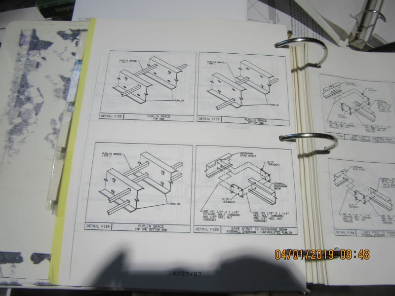
You still use the AISI cold-formed design manual for calcs. The attached jpg shows one company's method of bracing the bottom and/or top flange as needed. Their purlins already had the slots punched in them for the angle tabs to bend down into to create the brace. I do not remember what manufacturer this was. Note the brace has to be real close to the flange you are bracing. You can brace a bottom flange by running a small continuous angle under the purlin and attaching it to the flange of the purlin.

Based on your picture, you may also need sag rods to keep purlins from sagging over time. This is more likely to occur when you do not have a low-slope roof (2:12 or less). Sag tends to occur on the higher pitched roofs.
IMG_2395_z4kplk.jpg
 
Thanks Ron for sharing.

I have found the calculations in AISI.

Can you please also answer one more question. If the flush type girts are welded to the columns. Then should we treat them as fixed at both ends?
 
I your purlins span between frames rather than set on top of them, then they will be pinned supports. The only design guide reference I know of is the cold-formed design code published by AISI.
 
Where are you buying your purlins? In some parts of the world, they are just sold, in other parts the suppliers provide support. I would ask the supplier for installation details and load tables.
 
Just wondering, are these custom purlins? If not, surely the manufacturer has load-span tables for each of the section shapes and thicknesses??

If so, select the appropriate section size from the tables, and no member design is required from your end. The tables should also give an indication as to how many rows of bridging you need.

Apologies if this is not the case in America. I'm based in Australia and this is typical practice here. The manufacturer assumes design responsibility for the purlins themselves, provided you follow the span tables correctly.

EDIT: Link to a typical purlin/girt manufacturer catalogue complete with typical connection details and load-span tables (Australia)
 
hookie66 and Harste :

We use C-channels as purlins. Therefore, designing is required by us for the selection and purchase of members.
 
You will find load tables for C sections in the Lysaght tables which Harste linked for your use.

But if you mean hot rolled channels, use the structural steel code for your area. If you are using US standards, it would be AISC, not AISI.
 
Not calculations, but a lot of design information for columns and beams. For calculations, you need to use your engineering education and training.
 
Hamy, AISC is not the code authority for cold-formed steel. AISI (American Iron and Steel Institute) is the code authority for cold-formed steel. You will not find any design information from AISC as it relates to cold-formed steel like Z-purlins or cold-formed channels.
 
AISC provide calculations of beams and columns and much details. I frequently use it in my work. But i didnt find any purlin details thats why i was asking. i think its not in AISC manual.
 
Hamy, part of this is terminology. Purlins and Girts and the exact same thing from a structural standpoint. They are beams and if they have strut loads also, they are Beam-Columns. When you decide to put these beams on a roof, they are called purlins. If you put them on a wall, they are called girts. But they are still beams. If you decide to make them out of a Z-shape, they are Z-purlins or Z-girts. If you decide to make them out of Channels, they are C-purlins or C-girts. If you decide to make them out of mill steel, they are designed via AISC. If you decide to make them out of cold-formed, they are cold-formed Z-purlins etc. and are designed via AISI.

So you will not find any AISC design formulas for purlins or girts but you will find them for beams, columns and beam-columns. It is the same thing.
You will find AISI referring to purlins and girts at times because so many of these components are designed by AISI.
 
Status
Not open for further replies.
Back
Top