Continue to Site

Eng-Tips is the largest engineering community on the Internet

Intelligent Work Forums for Engineering Professionals

  • Congratulations KootK on being selected by the Eng-Tips community for having the most helpful posts in the forums last week. Way to Go!

Pushing work w/ threaded rod + hand crank

Status
Not open for further replies.

Vindicit

Mechanical
May 24, 2016
38
I'm kind of having a brain fart here. I'm trying to design a fixture that can push/pull work by using a long screw + hand crank. The screw is threaded into a stationary block and at the end of the screw is the work piece that needs to move back and forth. What I am having trouble visualizing is how the screw can attach to the work piece by means of some swivel action so the screw just pushes/pulls the piece and doesnt attempt to rotate the work piece while also being capable of pushing/pulling with at least 100 lbf. A normal screw and thread should be able to handle that force but the means of connecting the screw to the work piece is what I cant visualize.
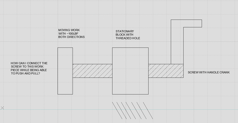
PIC_rk0qrt.gif
 
Replies continue below

Recommended for you

Drill a counter-bored hole in the work piece and a threaded hole in the end of the threaded-rod, and then attach the threaded-rod to the work piece using a shoulder-bolt.

220px-Counterbore_hole_stainless_steel.jpg


shoulder-bolt.gif


John R. Baker, P.E. (ret)
EX-Product 'Evangelist'
Irvine, CA
Siemens PLM:
UG/NX Museum:

The secret of life is not finding someone to live with
It's finding someone you can't live without
 
Sounds like a bearing attached to some sort of mounting device. Any further detail depends on the detail of the requirement.

Do you know how receptive the work-piece is to attachments (does it have a handy ferrous pad that could take a magnetic mount, or stud holes in just the right place), whether the device is going to have to support the weight of the work-piece, whether it will need to stop it tipping as well as pushing it and whether there is something to react the friction forces in the bearing (because otherwise the work-piece will still be prone to spinning)?

A.
 
Yeah, this is highly dependent on what you're trying to do, how much external guidance your load has, frequency of operation, what your precision of fabrication is, etc.

Anything you screw onto/into the end of the shaft will unscrew itself quite quickly as soon as you try to pull the load. In fact, anything with a threaded connection is a bad idea.

There will always be some torque transferred from the screw to the workpiece. If the workpiece is just hanging off the end of the screw it's gonna spin.


-handleman, CSWP (The new, easy test)
 
Through hole in work, cut grooves in the rod and circlip on both sides?
 
Hi

Have a look how a bench vice works.

“Do not worry about your problems with mathematics, I assure you mine are far greater.” Albert Einstein
 
I use J Baker's method often, when the load is constrained to move in a linear fashion. You can minimize the torque transmitted with thrust bearings if needed. You could also use something like a ball joint if you need more degrees of freedom for rotation of the load.
 
What you need is called a thrust bearing arrangement. That will allow the screw to rotate about its axis but not move laterally.
 
Thanks guys. I am going to look into using the shoulder screws with thrust bearings to see if that can fit into my fixture dimensions. Can I clamp down onto thrust bearings or do I need to be somewhat gentle with them? I typically dont like being too rough with bearings but these seems like they would have a fair bit of force being pressed onto them.
 
Is one direction more prevalent ?

Got an OEM jack in your car for tire changing ? If it is some variation of a scissors jack, there will be some thrust bearings of varying complexity, retained in in various ways.
 
Yes in this fixture the force will be mostly one direction, the opposite direction will probably just be a return.
 
Status
Not open for further replies.

Part and Inventory Search

Sponsor