bekske
Automotive
- Mar 26, 2018
- 2
Hello everybody,
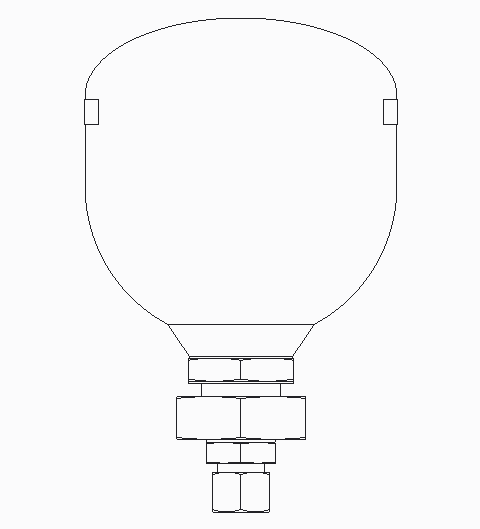
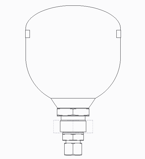
We recently started using Catia at our company (development of chassis for busses) and with making drawings I've come to a problem that was easily solved in Creo (our other CAD program) I'm making a drawing of the fixation of the front axle and want to use the chassis as a reference. So I see the front axle as a normal line and the complete chassis as a light grey dotted line. Something as in the pic's attached( this is done in creo). I've already read to put two views over each other and then change the view from the chassis in the desired line style. But then I can't attach dimensions between these two views.
And how does it work with the bom table? If I make a new assembly with the chassis and axle then I get two items in the table. In creo we hide the chassis and make the axle flat (so we see all the parts in it) and then attach the balloons
Anybody with a good tip on this one?
thanks,
Berry


