Continue to Site

Eng-Tips is the largest engineering community on the Internet

Intelligent Work Forums for Engineering Professionals

  • Congratulations waross on being selected by the Eng-Tips community for having the most helpful posts in the forums last week. Way to Go!

Pylon Sign Footing Design 1

Status
Not open for further replies.

Joshiru

Civil/Environmental
Feb 7, 2017
5
Hello Engineers,
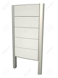
I have been asked to design a pylon sign 6m(high) 2m(width) Supported by two metal columns (not sure yet if I beam or Tube) and closed my signs. I'm using a wind speed of 60 m/s and I try to get the reactions on the support using STAAD.Pro. During the manual computation for the design of the combined footing I get a negative reaction on bearing (The moment is too strong due to the wind and the Weight of the structure is Small). I asked some of my co-workers and they said to increase the size of the footing to get a positive bearing reactions however on site I cannot Increase the size due to some limitations. what else are the other solution for this? And another question on equation e=M/P is soil weight, footing weight is included on P?
download_gskwui.jpg
 
Replies continue below

Recommended for you

Drilled pile(s)

Reaction to change doesn't stop it :)
 
Embed a steel section with a cap connection plate on it in a drilled concrete pier (caisson). Then bolt the base plates of the sign structure to that cap plate. You can likely make a 24"-diameter pier work for most typical sign sizes, and there are many contractors (including electrical ones) who can drill 24" holes.

Thaidavid
 
It's generally alright to have your footing partially uplift from the soil so long as:

1) the whole thing doesn't flop over.
2) the soil isn't overstresed.
3) the footing is designed for the assumed condition.

And yes, you can include soil overburden and footing weight in P for the eccentricity calculation.


I like to debate structural engineering theory -- a lot. If I challenge you on something, know that I'm doing so because I respect your opinion enough to either change it or adopt it.
 
If it's OK with the client, I'd use drilled piers with your main vertical members embedded the full depth of pier. Pipe would probably be cheapest if the cabinet manufacturer is OK with it. They can install the sign cabinets over/around the pipes in segments. But this construction practice can vary on region. One big benefit to this is the simplicity. They only have to install two pipes that are plumb and at a specific spacing. All other adjustments can be done during the install of the cabinets and there's usually quite a bit of tolerance for field fitment.
 
Or just straight up make your footing thicker, increasing the dead weight significantly. But any increase in plan size will do wonders.
 
I would make sure that the overturning moment is less than the moment resisting. Its an easy first principals hand calculation. Usually a large pad footing can be used with thick column base plate and cast in H/D bolts to fix the column base. If you don't get the capacity from thickening the footing and cant increase the plan size then deep concrete piers are probably needed to resist the overturning moment.
 
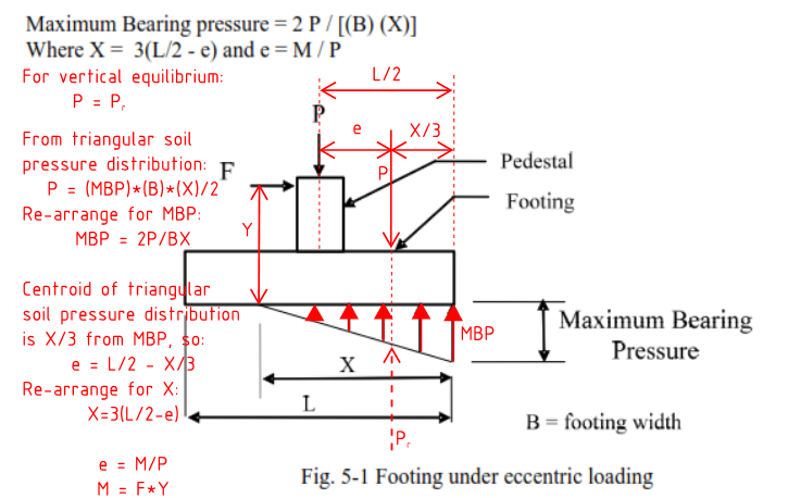
Thank you for your suggestions! Actually my reference from designing the footing is from "Footing Design by S. Ali Mirza and William Brant". can someone confirm this because I didn't encounter this during my college years (picture below). I asked my boss about piles but he didn't like it due to higher cost so i'm designing a solid foundations.

Eccentric_wr9g5m.png
 
Joshiru said:
my reference from designing the footing is from "Footing Design by S. Ali Mirza and William Brant". can someone confirm this because I didn't encounter this during my college years (picture below)

Looks right to me:

ECCENTRIC_FOOTING_asyfzi.png
 
Agree with the drilled pier recommendations. I've designed lots of these for high wind areas and sometimes the required large footings just won't fit!

Note that the drilled piers we are discussing are NOT piles and are comparable in price to large footings, sometimes even less expensive. As thaidavid40 notes, many electrical contractors and even general contractors can do these relatively small drilled piers. Most often, an 18 to 30 inch diameter pier, with a depth of 10 feet or less will suffice. Remember you need a 1.5 factor of safety for overturning under most US codes.
 
Big spread footings are incredibly inefficient for sign foundations due to the high overturning moments and lack of dead load. From my perspective they're a last resort option when piers or deeper excavations that utilize lateral bearing won't work for some reason. Even a big trench footing that uses lateral resistance would likely be more efficient than a mat that's trying to resist overturning. And the footprint is quite a bit smaller.
 
Actually this sign is for our company (Contractor) and we will do the construction. We don't have the equipment to drill piers as you recommended. And my boss don't want to contact other contractor to drill piers because he believes that it will cost more.

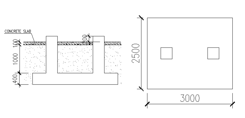
I have another question, due to lack of Dead Loads I increase the Height and depth of the footing to 1.5m H and 0.4m D and increase the dimension to 3m x 2.5m. using the method posted on my previews reply this is what I get (e=0.537m, x=2.138m, Qmax=77.785KPa) and the Factor of Safety Against overturning is 2.04. I'm just new on Designing and this is good for me but I also want to ask if this is really good to go? Sketch below

Sketch_1_nnsxql.png
 
Just make a solid block foundation. You're a contractor, right? Concrete is cheap and its a pretty small foundation. By doing this, you will also have a large surface area to engage a lot of passive pressure and friction resistance.
 
Status
Not open for further replies.

Part and Inventory Search

Sponsor