Continue to Site

Eng-Tips is the largest engineering community on the Internet

Intelligent Work Forums for Engineering Professionals

  • Congratulations KootK on being selected by the Eng-Tips community for having the most helpful posts in the forums last week. Way to Go!

Question about crack representation in ABAQUS

Status
Not open for further replies.

Low12

Mechanical
Nov 20, 2019
22
Dear Abaqus users,

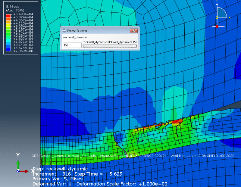
i am simulating crack propagation of a coating in conjunction with an indentor test. I was a bit surprised by the crack representation when i saw, that cracked elements would penetrate the slave body. You can see it in the picture i uploaded (the cracked elements penetrate the substrate (slave) which leads to a weird representation.
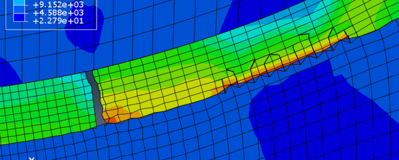
cracks_aqms1b.png


I am using a node to surface contact between the substrate and coating with a cohesive behaviour (damage and damage evolution). For cracks i use the XFEM with the cohesive zone model (crack initiation and evolution).

I would appreciate any tips.
 
Replies continue below

Recommended for you

It may be hard for the contact pair to handle contact with sharp surfaces of the cracked element. You can try adding general contact to your model.
 
Hey, thanks for your answer.

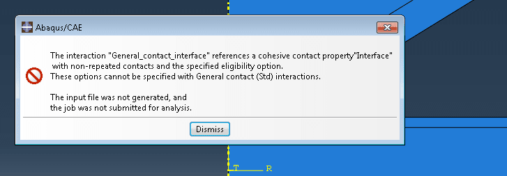
Unfortunately i get the following error when using a General contact in the interface:

Unbenannt_brjb21.png


Is cohesive behaviour possible with a general contact assignment? Before i was using a node to Surface contact with finite sliding and a cohesive interaction property to model the Interface between Substrate and coating.
 
Which version of Abaqus do you use ? Cohesive behavior for general contact in Standard was added in 2017 release.

This picture in your first post shows results plotted with deformation scale factor = 1, right ?
 
Hey,
i am currently using ABAQUS/CAE 2017 so it should be possible?
Yes, the scale factor is 1. Im wondering if there is another possibility to prevent this from happening. I tried a finer Mesh on the slave but unfortunately that also didnt help.
 
Cohesive behavior for GC in Standard will work in this version of Abaqus but you have to change the settings of this interaction as suggested in the error message.

Do you have normal and tangential behavior defined in addition to cohesive one ? If not, add them to the interaction property.

Also check the documentation chapter "Contact cohesive behavior", paragraph "Interaction between cohesive properties and regular contact properties".
 
Thanks for the tips, i already had tangential and normal behaviour defined in the contact property. I managed to get the simulation running with general contact (which in my understanding is just a surface to surface contact with finite sliding).


engtips_ycej56.png


Unfortunately as you can see in my picture the problem is not solved yet. I think this kind of crack pattern develops, because in the XFEM Domain, when the first crack penetrated the entire enriched region, the crack initiation criterion is reached in multiple cells during the same time increment which leads to multiple cracks emerging out of the same region.
I am still wondering why the split elements can just penetrate the neighbouring cells though, the simulation always aborts after ~5s while the actual indendation process is about 15 sec long.
 
Is enrichment specified only for this thin layer of coating between the indenter and substrate ? Adding small part of subtrate domain to enriched region may help because cracks will be able to propagate through the interface. Try this without general contact first.

Another documentation reference worth checking is paragraph "Defining contact of cracked element surfaces using general contact", chapter "Modeling discontinuities as an enriched feature using the extended finite element method". It may give you some hints regarding the use of GC with XFEM. You can try it if contact pairs don’t help.
 
Enrichment is only specified for the Coating so far. Thank your for the tip, in what way would adding XFEM to the substrate help ? It seems like cracks are already propagating through the coating.

Thank you i will read it.
 
Based on the picture attached to your first post it seems that with enrichment added to small region of the substrate can make the cracks propagate through the interface instead of ending in the coating and thus resulting in penetration.

It would be better to make the indenter rigid, if it’s not absolutely necessary to account for its deformation.
 
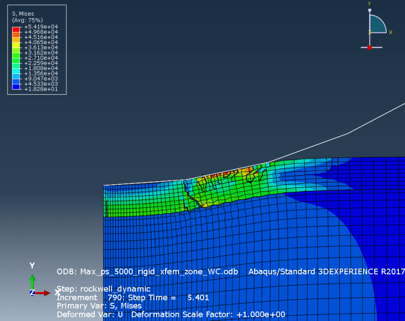
Hey, i added a small enriched partition to the substrate underneath, i also made the indentor rigid. Unfortunately the same Problem exists:

neu_engtips_fxxwff.png


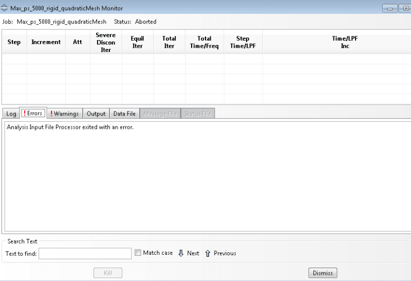
I am using linear elements, could this be a possible reason? The problem is, that i cant start the analysis using a quadratic mesh, it immediately aborts without giving a specific error:

error_cjnwmk.png


Is there a problem with Surface based cohesive behaviour and quadratic Elements?
 
There are some limitations when it comes to elements that can be used for XFEM analyses. In 2D simulation with propagating crack you can only use bilinear plane stress/strain elements (CPS4/CPE4).

Maybe you should adjust the damage initiation criterion a bit so that cracks don't form so easily.
 
Hey FEA Way,

the initiation criterion is quite low, yes. But i want the simulation to represent reality as closely as possible, so i dont think i can adjust it. The current problem for me is how to partition the coating. If i only use one XFEM enriched zone for the whole coating, only 1 crack emerges and new cracks only form, when the first crack propagated through the whole coating. But in reality multipe cracks will form, depending on when and where the initiation criterion is reached. Do you have any tips regarding partitioning an XFEM enriched region? Thank you for your help so far, youve been helping me a lot.
 
According to the documentation ("Modeling discontinuities as an enriched feature using the extended finite element method" —> "Defining an enriched feature and its properties"), if you have a single enrichment zone then multiple cracks can occur only when the damage initiation criterion is fulfilled in several elements in the same time increment. Otherwise new cracks won’t appear until all previous cracks have propagated through the boundary of the enriched zone. If you want to have multiple crack nucleations appearing sequentially at different locations then you should define more than one enriched zone.

It seems that there’s a significant hourglassing visible in your results. Try eliminating it first.
 
Status
Not open for further replies.

Part and Inventory Search

Sponsor