Continue to Site

Eng-Tips is the largest engineering community on the Internet

Intelligent Work Forums for Engineering Professionals

  • Congratulations KootK on being selected by the Eng-Tips community for having the most helpful posts in the forums last week. Way to Go!

Question about local mesh refinement

Status
Not open for further replies.

Adil Memet

Mechanical
Mar 12, 2023
34
Dear All,
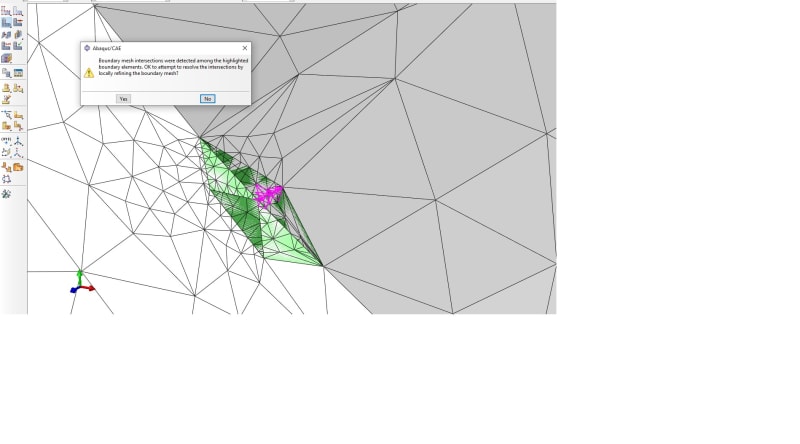
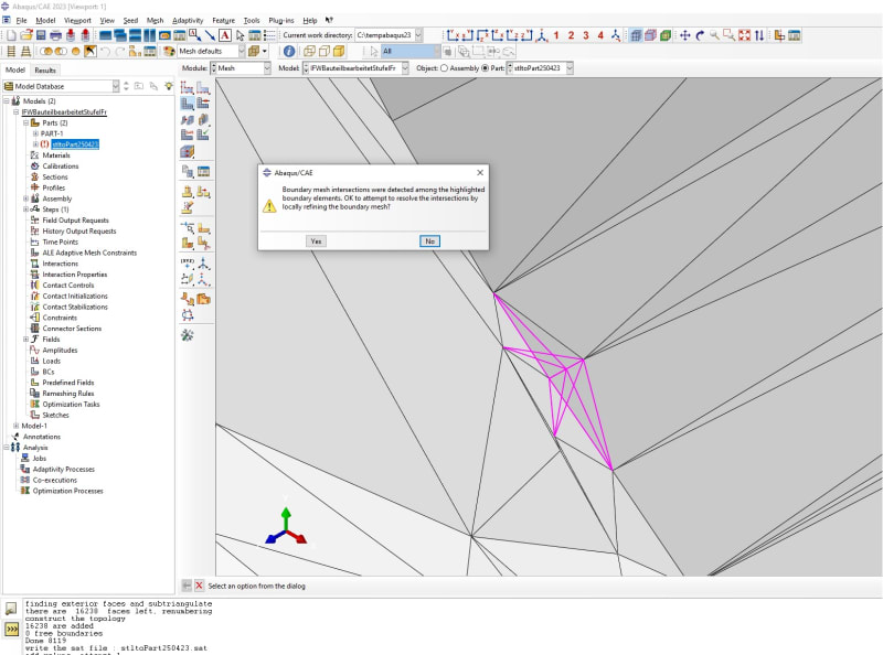
I have a question about local mesh refinment, I have a mesh data file as STL format, after importing it and remesh it (generated by House coded software, due non-closed loops in the mesh element it shows some error ;), to run a simulation, Abaqus give me some warning as well as error message (Intersection mesh problem. after which, I locally refined it by selecting some specific mesh it biased seed . at the end, I still face similar problem. has anybody has been experienced similar problem ? Thank in advance.
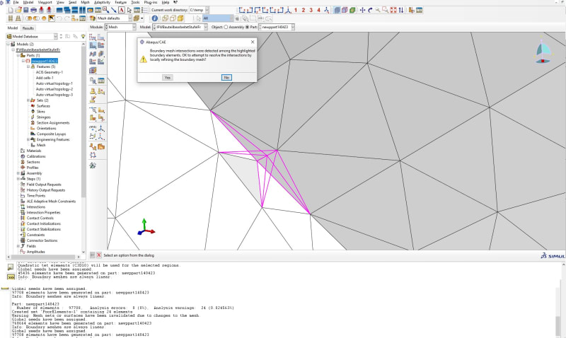
meshintersection_jn9hjh.jpg


newmeshintersection_wfirnb.jpg
 
Replies continue below

Recommended for you

It's hard to say based only on those pictures (it would be best if you could share the file) but there indeed seems to be some non-manifold or otherwise broken mesh region. In fact, STL format is problematic in FEA. However, Abaqus offers some tools to handle such geometries. Check the article "Meshing Complex Geometries in Abaqus" on the Simuleon blog and consider using tools like the 3D Mesh to Geometry plug-in and Virtual Topology to get rid of the initial surface mesh defining the geometry and generate proper solid mesh for analysis.
 
Thank you very much for your info and there is files you asked for. Please have a look. Thanks.

STLtoMeshproblem_kedxu1.jpg
 
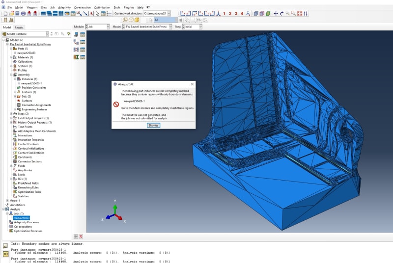
After fixing mesh error or warning problem.there is some information during Job Running . some elements in the boundary has not completly meshed.

BoundaryElemenet_g1hyx4.jpg
 
You have to create a solid (or shell but it's unlikely to be the case here) mesh if you haven't done it yet. What you import to Abaqus is just geometry. Represented using surface mesh but not finite elements.
 
Thank you very much for your quick reply, indeed, I did import STL-Import ---> Generate geometry from mesh then remesh it, how to create Solid mesh then ?
 
If your geometry is still just a surface, use Shape --> Solid --> From Shell. Then, if needed, use Virtual Topology to remove redundant faces. Finally, go to the Mesh module and generate a solid tetrahedral mesh for this part.
 
Thank you very much for your tips, I will try as you said
 
Hello again
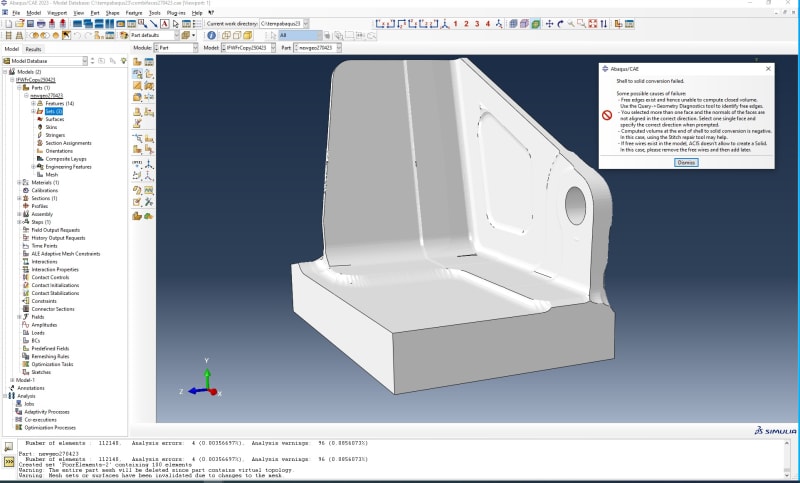
I tried the method you mentioned, at the end, I got this message, looks like this one also not working as I expected. what I can do the next step ?


ShellTOSolid_xy6icc.jpg
 
First repair that invalid region highlighted in the beginning. Geometry Edit —> Face —> Remove and Cover edges tools are sufficient for that. Then the previously described procedure should work.
 
Hello,
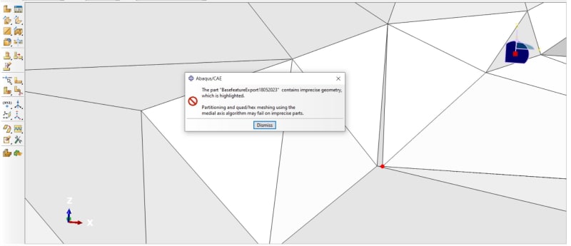
Thank you very much for your tips regarding to remove process, in some cases, I just have one single point problem like the one shown in the below, how to remove that one single point or line elements from the converted geometry. Thanks in Advance.

Pointmeshproblem_suxsy4.jpg


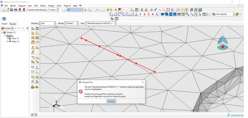
in the case of line mesh problem. how to remove it ?

ImpresiseGeometry13052023_iujsjl.jpg
 
Those highlighted points and edges likely belong to some incorrect surface elements so the solution described above may still be relevant. Try using the Geometry Edit tools to fix those regions (e.g. replace that narrow element in the top picture).
 
Status
Not open for further replies.

Part and Inventory Search

Sponsor