Continue to Site

Eng-Tips is the largest engineering community on the Internet

Intelligent Work Forums for Engineering Professionals

  • Congratulations KootK on being selected by the Eng-Tips community for having the most helpful posts in the forums last week. Way to Go!

Question regarding car dealership canopy

Status
Not open for further replies.

generick

Structural
Sep 3, 2021
27
Hello all,

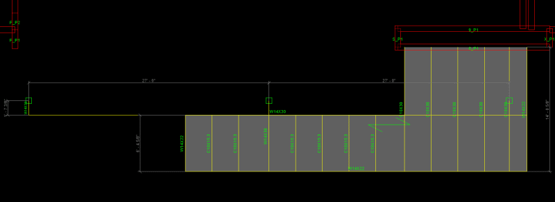
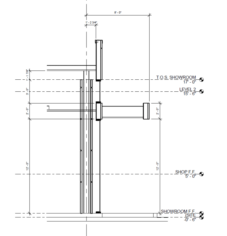
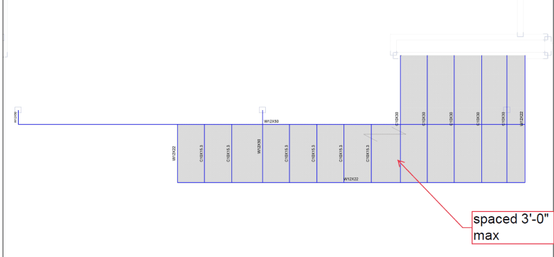
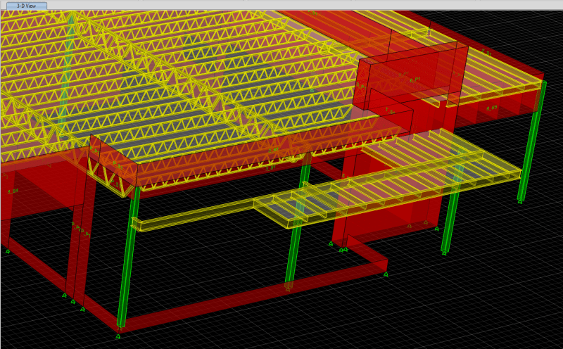
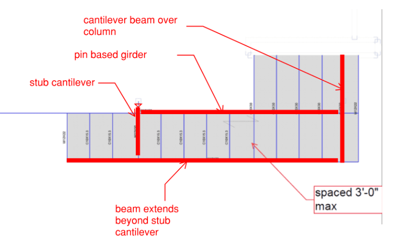
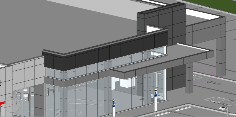
The architects want to achieve this canopy look as you see below as well as a section cut and I am trying to come up with a way to frame this out. I have also attached my extruded ETABS model for more clarity of my intent. Essentially, I was looking to tie the cantilevered frames (mix of C and W steel shapes) back into a steel beam that is hidden in the fascia which also ties back to the main interior steel columns. The roof set-up is an OWSJ with a metal deck with concrete topping. The canopy itself will most likely be of gypsum ceiling board.

Do you guys have any practical or easier framing get-up to go about this?

Thanks!
canopy_ityaic.png


dim_dpfndm.png


canopy_1_fvmr14.png


canopy_3_sa51nc.png


canopy_2_ic0juu.png
 
Replies continue below

Recommended for you

That primary girder wants to be tube steel - much better in torsion. Even if the stresses work out in an open section, you're going to have a lot of twist that'll make the tip of the cantilever droop.

Why are you putting concrete on top of a canopy?
 
Hello,

Thanks for the inputs so far.

@MIStructE_IRE - I have designed my main columns with the addition of the moments from the cantilever. In terms of torsion of the primary (if you're referring to the main steel beam that runs E-W in plans), I haven't done much work yet into this, however, I am reconsidering making this a tube steel if that helps with anything.

@phamENG - I agree, just to clarify, that primary girder you're talking about is the long-spanning steel beam hidden in the fascia? I also meant to say my roof is a metal deck with concrete topping and the canopy as of right now is most likely going to be gypsum ceiling boards. I might have mixed up the two, however, I have edited the post thanks to that.
 
Transferring the load via torsion (even with a hollow steel section, is rarely a suitable means. You either need big members and moment connections into the centre column or tell the architects that they need a column in the bottom left of the canopy.
 
HSS tubes for torsion, for sure. You are likely looking at 100 psf snow accumulation (even in Florida). All surfaces will have to be insulated to prevent transmission of frost to the inside. Deflections because of the torsion can be great... everyone seems to get the neat projects... I just get simple boring ones. [pipe]

Rather than think climate change and the corona virus as science, think of it as the wrath of God. Feel any better?

-Dik
 
@human909 - I agree, torsion was already a big player when I first saw this canopy. I think we may have to compromise with the addition of the columns at the bottom left just as you said. I was just trying to make it work before looking into the addition of the column.

@dik - No snow that concerns us, rather, we are in the tropics! Exchange snow for corrosive environments. Anyways yes, I might just propose an extra column towards the bottom left of the canopy to negate severe torsional effects.

Is there a way to tag people in terms of responses in this website? I'm not sure if there's another way to do so other than manually calling your names out.

Thanks again for all your inputs.
 
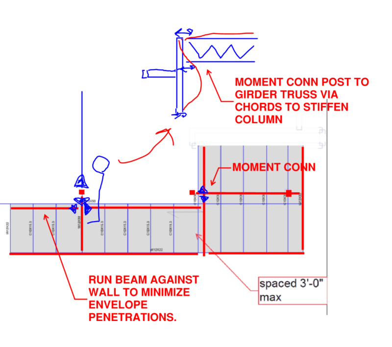
Can you replace the OWSJ at the roof with a structural member and have a vertical member running up to the roof, forming a moment connection in the shape of an L? Looks like you could get away with that and eliminate all torsion. I made an ugly sketch attached, you're just left with a cantilever where the architect wants a window to nowhere.

 
 https://files.engineering.com/getfile.aspx?folder=55bac350-5310-4dd8-a9f2-7ba94d713eed&file=Capture.PNG
@canwesteng - not sure if I follow, however, your sketch looks a lot similar to the sketch of sticksandtriangles. Is this similar to what you were trying to convey? I'd like to keep the OWSJ system intact as the parapet wall at the roof level gets supported off the concrete deck. I have been looking to explore options of turning the columns you see into concrete columns since they are HSS columns cladded but I am still brainstorming as we speak.

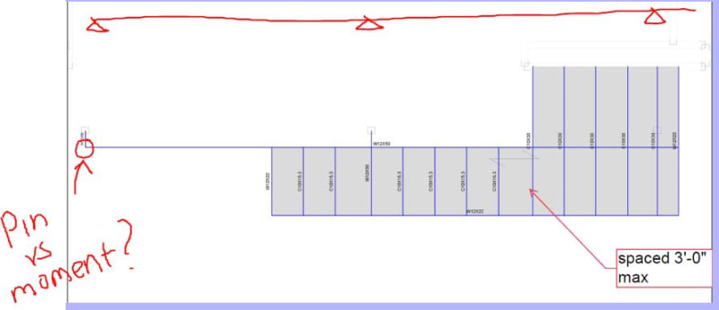
@sticksandtriangles looking into the overall plan of the canopy. Would the primary girder (E-W) boundary conditions be fairly represented in this sketch below?
sticks_and_triangles_bexrs7.jpg
 
Can you eliminate the concrete to help keep the loads manageable?

The first rendering also shows two columns throughout the length of the canopy inside the building, your analytical model only has one. It would be of benefit to you to have another column available. As it is, I don't understand how you're planning on supporting the high roof at the bottom right corner.
 
I'd have laid this up exactly how sticksandtriangles shows. Stub cantilever off the columns and propped cantilever the perimeter beam off of those. You'll still need a continuous member running around the storefront below the ribbon window above the canopy - I'd use a HSS for that.

Also, OP, your Revit model shows 3 columns behind the storefront, all your other sketches only show 2?

 
One other item to be aware OP, be sure to check these wind girt columns with P-Delta turned on in your analysis model. These spindly HSS columns with large out of plane point loads and sometimes large axial loads can often have moment magnification in the range of 1.2-1.3 vs. a simple linear elastic analysis that does not consider P-Delta.

S&T -
 
Status
Not open for further replies.

Part and Inventory Search

Sponsor