Continue to Site

Eng-Tips is the largest engineering community on the Internet

Intelligent Work Forums for Engineering Professionals

  • Congratulations cowski on being selected by the Eng-Tips community for having the most helpful posts in the forums last week. Way to Go!

Unusual Canopy Connection 11

dik

Structural
Apr 13, 2001
26,010
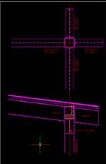
I have an unusual canopy connection with W12x30 beams framing into an HSS 8x8x0.375 column. They connect at different levels. There is a continuation of the beam on the opposite side of the column. I'm planning to field weld 5/8" end plates on the beam ends to the face of the columns as shown. Does anyone have any concerns about this approach? Worked a better approach. Thanks...

1744343427603.png
 

Attachments

  • 1744340023563.png
    1744340023563.png
    35.7 KB · Views: 25
Last edited:
Replies continue below

Recommended for you

Thanks gentlemen, it works.
View attachment 8164
What size of flange plates are you using for this? I ran a quick check in RISA Connection, and I'm noticing some differences in your approach. Notably, they are taking ro as being 1.5tr, not 3.0tr for the local yielding of HSS side walls. They also appear to be using different equations, unless they/you have simplified it in any way; the one most different is the HSS Column Transverse Plastification, or your Rn1.
 
BAR 5/8x6 for the large moment and 1/4" fillet welds and BAR 3/8 x6 and 3/16 fillet welds for the small moment. Does RISA list the formulae it uses? It still works at 1.5 for ro
 
Last edited:
BAR 5/8x6 for the large moment and 1/4" fillet welds and BAR 3/8 x6 and 3/16 fillet welds for the small moment. Does RISA list the formulae it uses?
They are showing AISC 15th edition, Eq 9-30 for that specific calculation. What reference did you use? The value is MUCH smaller in RISA (not so small to become the governing limit state however).
 
Are you just checking the tube wall itself or the fact that the deflection of the tube will stress the crap out of the welds that connect it to the plate as the plate will not match the deflected shape of the tube wall?

It's been a while since I've done something like this but my recollection is that the AISC procedures account for that as something like a 25% increase in weld demand to account for the non-uniformity of weld stress that you've accurately identified. That's always struck me as a bit of a crude tool for the job but, if it's good enough for AISC, it's usually good enough for me.
 
When I compare the moments coming into the joint, it has this flavor:

1) VLFRS moment frames coming from both sides with the column in question common to both.

2) Pretty nominal moment connections for the overhangs.

Is that accurate? If it is, this feel like some sketching EOR'ing to me. That two way moment connection is a big ask at the best of times but especially when it's:

1) An HSS column.
2) The beams come in at different elevations.
3) One of the moment frame beams is pitched.
 
So this phenomenon is similar to a standard moment frame where an I-beam sits on top fo a column. We typically add web stiffeners to the beam to prevent the bottom flange from doing the same thing (albeit reversed) as the tube wall in Dik's project. Is there AISC guidance on this when you would need to reinforce the flange of the I-beam with stiffeners?
 
So this phenomenon is similar to a standard moment frame where an I-beam sits on top fo a column. We typically add web stiffeners to the beam to prevent the bottom flange from doing the same thing (albeit reversed) as the tube wall in Dik's project. Is there AISC guidance on this when you would need to reinforce the flange of the I-beam with stiffeners?
AISC design guide 13 and the Seismic Design manual have ample examples.
 
Just throwing out an idea here, working from the perspective of prioritizing the capacity and stiffness of the two significant moments.

c01.JPG
 
They are showing AISC 15th edition, Eq 9-30 for that specific calculation.
The capacity based on 9.30 is OK...
It's been a while since I've done something like this but my recollection is that the AISC procedures account for that as something like a 25% increase
I have built in more than 25% for my own comfort.

"Are you just checking the tube wall itself or the fact that the deflection of the tube will stress the crap out of the welds that connect it to the plate as the plate will not match the deflected shape of the tube wall?"

Deformation in the column will be limited by the rotation of the beam.
1) An HSS column.
2) The beams come in at different elevations.
3) One of the moment frame beams is pitched.
You summed up my concerns...
AISC design guide 13 and the Seismic Design manual have ample examples.
...already checked that one. It's 'done like a dinner'; I'm just waiting to see if Brian can run the FEM. Final Design...
1744662630835.png
 
It's 'done like a dinner'; I'm just waiting to see if Brian can run the FEM. Final Design...
My 3D FEM program, written in Fortran 50 years ago has seen some marvellous projects. I've used it for tip potentials for microelectrodes inserted in the cerebral cortex. It's also been used for designing gas bearings using piezoelectrical ceramics so they work as physical bearings at low revs and gas bearings at high rev. It's also been used for studying amalgam filling failures due to tensile fatigue caused by steel pins inserted in teeth. This was the first time I used statistical analysis because measurements were done using LVDT and in the micron range.
 
Does RISA list the formula used that gives the low value? I'd be curious to see what it is.
They are showing AISC 15th edition, Eq 9-30 for that specific calculation. What reference did you use? The value is MUCH smaller in RISA (not so small to become the governing limit state however).
equation.png

This is one of the equations among many others they check. But this is one that is different from what you used; it doesn't use beta's or n's.
 
My 3D FEM program, written in Fortran 50 years ago has seen some marvellous projects. I've used it for tip potentials for microelectrodes inserted in the cerebral cortex. It's also been used for designing gas bearings using piezoelectrical ceramics so they work as physical bearings at low revs and gas bearings at high rev. It's also been used for studying amalgam filling failures due to tensile fatigue caused by steel pins inserted in teeth. This was the first time I used statistical analysis because measurements were done using LVDT and in the micron range.
Well, I can beat that.
My 2D frame program is from 1984 and I have been using it daily since 1991. Even has a really nice GUI - since it is on a Mac.
 
Thanks... it's 9-30, I've already included it.
Well, I can beat that.
I'm not so sure... my first 2-D frame program was written so it could run in 64K RAM by swapping 5-1/4" floppies.
 

Part and Inventory Search

Sponsor