Eng-Tips is the largest engineering community on the Internet

Intelligent Work Forums for Engineering Professionals

  • Congratulations waross on being selected by the Eng-Tips community for having the most helpful posts in the forums last week. Way to Go!

Question regarding Roll Centers of a Double A-Arm suspensions

Status
Not open for further replies.

MiquelSants

Nuclear
Oct 29, 2014
5
Greetings.

As per the title, the question is as follows:

If I'm facing the car up front, the procedure to determine the IC's and finally the RC seems simple:
- extend lines from upper control arm and lower control arms, check their intersection point
- repeat the step above for the others side
- from the IC's, extend lines to the center of the contact patch of each tire
- where these lines intersect, we should find the RC's

However, on a double a-arm assembly (as depicted here:Link) , each arm (upper or lower) has 2 different attachment points to the chassis.

As such, how to draw the lines from upper and lower arms (so they intersect (if they intersect) and we can find the IC's), considering that there are 2 attachment points to the chassis?

I am aware this is a "basic" question, but I'm trying to figure out exactly how to implement this in my tools (I'm a also a programmer). I am also intent on checking the 3-dimensional coords of IC's and RC's, and not only the usual width & height locations of these.

Thank you for any help.

MS
 
Replies continue below

Recommended for you

ps:

Just came up with an idea for a slider type adjuster mechanism using a stepper motor (as used on CNC mills) to actively adjust all the inner suspension pivots during driving. I've got the sliders designed but have to figure out how to size and mount the stepper motor.

Bo
 
BUGGAR said:
Just came up with an idea for a slider type adjuster mechanism using a stepper motor (as used on CNC mills) to actively adjust all the inner suspension pivots during driving. I've got the sliders designed but have to figure out how to size and mount the stepper motor.

If you want a suspension with inner suspension pivots that have variable locations, you might be interested in the Camber Compensation & Anti-Roll suspension design. It's simple and, according to comments found online, it seems to work well.
 
Camber Compensation & Anti-Roll Suspension

That looks like a challenge to design - I have to try it!
I couldn't find anything on the correct geometry for this linkage and hope to have some time to search the patent drawings. I tried to draw some vector diagrams last night and couldn't figure it that way. Time to break out the all-thread and carburetor ball joints to make a model.

I gave up on the inner pivot slider mechanism since it has to operate on an arc to match the length of the control arm; difficult to do with a straight line screw mechanism. Besides, I have a new toy to play with - CC&AR linkage.

ps: anybody ever seen a curved screw mechanism, kinda like that curved Pontiac Tempest driveshaft from years ago?

Bob
 
The CCAR system is interesting. I suspect that getting the geometry right will require tinkering with a model until you get it to work right - dependent on track width, length and position of arms, length of steering knuckle, etc. Another thing that I can see with this, is that there will be no choice in how high up the steering knuckle that the steering tie-rods attach. If the tie-rod is anywhere other than in line with the lower control arm, there are going to be some interesting bump-steer and roll-steer effects.

With most newer production vehicles designed to be driven by everyone (i.e. relatively unskilled drivers), the front suspension often intentionally has a not-so-great camber curve in the interest of ensuring that the vehicle always understeers. The rear suspension often is trailing-arm-based, in the interest of counteracting the back end lifting up when braking; that's not really consistent with the use of CCAR either. If having the rear wheels stay flat to the ground is an important issue and you want a high-ish roll center then you can just use a beam axle (or deDion axle), which has far fewer pivot points and bushings and links.
 
O.K., here's my adaptation of the CCAR to a Locost type chassis. I have no idea what the linkage geometry should be. Does this thing mean I can use parallel control arms? Equal length control arms?
Also, how will I design that link to restrain control arm longitudinal (parallel to vehicle) forces? I have an idea but it's getting complicated.

This is fun but too many questions to be practical for me.

Jay, what's your current project?

Bob

Let me know if you can open this file. Since I fixed my computer, I can't download.
 
 http://files.engineering.com/getfile.aspx?folder=566a093c-5a6c-4566-aa5c-ac41a9ca65cc&file=CCAR.pdf
Greg
Are you able to provide more information on the estimation/determination of the force based RCH without a full analysis of the system?

Cheers

Rowan Carter
 
Bob
My current project is a rear suspension for a project car which is roughly based on an early Corvair.
It has about 1400 pounds on the rear, about 1000 lbs on the front.
My UCAs will carry the spring load, and is well along in fabbing, so any redesign will come much later.
Enough of it is bolt-together, I can go to a CC&AR configuration later.
The engine is transverse, but there is room to package the cross-links pretty easily.
The front suspension is not really an issue, given the weight distribution. It will stick well enough regardless.


Jay Maechtlen
 
For a rear CCAR system, I wonder out loud what the real net benefit is, compared to using a deDion beam axle.

An axle also keeps the wheels upright to the road no matter what the bodyshell does, and it also allows higher roll centers without jacking.

Is a CCAR system a much-more-complex deDion beam axle?

I suppose the CCAR system would allow you to control toe with wheel travel, whereas deDion locks the wheels parallel. But if you are designing for zero bump steer, that's what is going to happen anyway.
 
Jay, will you be using swing axles like the Corvair, or the later Corvair suspension? And what kind of engine?

Brian, I have to agree that the deDion seems to do the same thing as the CCAR. A long time ago, we had trouble with solid axles "tramping". I presume the deDion eliminates that issue.

Bob
 
Bob:
Mine's a transverse GM 3800 V6. (transplanted FWD setup). Lower control arms, going to upper control arms instead of struts.

Greg:
I didn't find much info on camber sensitivity with a quick Google search. Can you suggest sources?

Thanks
Jay

Jay Maechtlen
 
@Rowan- FBRCH is an output from a K&C test or simulation. If you want to do it as a hand calc then you need to account for the stiffness of the suspension mountings, the camber stiffness of the wheel/bearing/spindle assy, and the lateral stiffness of the tire and wheel.

Here's what W Mitchell says, a good start


There are innumerable threads on fsae, f1technical, and here on much the same subjects.

Years ago I was very keen on promoting FBRCH rather than kinematic, but in fact for small geometry changes kinematic is useful, and for serious maneuvers neither is amazingly helpful,I think, and millimetric accuracy is almost certainly excessive.


Cheers

Greg Locock


New here? Try reading these, they might help FAQ731-376
 
Greg, thanks for the reply. I have a basic understanding of the subject, and have read Mitchell's article before - and I agree it's a good introduction. I noticed you FBRCH formula above and was just wondering how much the different approaches affect design decisions. I appreciate your point regarding serious maneuvers.
I'm currently reviewing the angle of the LCA on a MacPherson strut club type racing car, and was keen to try a lower RCH to reduce initial weight transfer on turn-in. In the past I've always always set up the vehicle with a level or down sloping LCA due to a belief that an up sloping LCA caused too much RC migration or an underground location etc.

Cheers
Rowan Carter
 
"I'd work back from the desired tire inclination angles "

Hi Greg,

Is that more than actual tire on road camber, and can you share what angle modern widish street tires might prefer?

thanks

Dan T
 
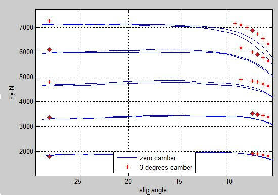
Yes, we know the tire needs to be roughly square to the road, or leaning into the turn a little at the top. How much would depend on the exact tire, I don't know, but 3 degrees doesn't seem to be dangerously outside of a reasonable figure.

u7fdh7o6h2bq9lb6g.jpg


shows raw F&M data for a tire at various Fzs, with 0 and 3 degrees of inclination angle.


Cheers

Greg Locock


New here? Try reading these, they might help FAQ731-376
 
Hi Guys,

This might be interesting for you. Some time ago I stumbled into a website with a vehicle dynamics tool in excel and asked here on the forum whether anybody had experience with the tool. I did not get that many answers so I hesitated. Anyway, after a while I decided to buy the base ride and handling setup tool and I did indeed learn a lot on vehicle dynamics by using it. Recently I did buy the fully excel based Suspension Design Module that does allow you to investigate/create all kinds of suspensions and I am really loving it. The tool is called "Dynatune Suspension Design Module" for those who might be interested.

Regards,

Sam
 
That CCAR is pretty interesting. In a situation where the tires always need to be coplanar, it would work really well. But think about clipping the apex of a turn on the track with the inside wheel, and having your outside tire suddenly being forced to camber positively, while the entire car is shifted onto a new plane magnifying the tires positive camber condition. Positive camber being magnified by body angle changing relative to the road would cause the outside tire to lose a lot of lateral grip. CCAR looks a really complicated way to re-create all of the advantages and disadvantages of a solid axle, while also complicating your options for mounting a steering rack and adding moving parts. Linkage bearings need to be kept up on, and they would inherently be hard to reach in a vehicle with a CCAR system.

I think that the effects they were looking for would more easily come from parallel and equal length A arms with the strut towers mounted with consideration to the RC moment arm and center of gravity

"Formal education is a weapon, whose effect depends on who holds it in his hands and at whom it is aimed." ~ Joseph Stalin
 
Status
Not open for further replies.

Part and Inventory Search

Sponsor

Back
Top