Continue to Site

Eng-Tips is the largest engineering community on the Internet

Intelligent Work Forums for Engineering Professionals

  • Congratulations SSS148 on being selected by the Eng-Tips community for having the most helpful posts in the forums last week. Way to Go!

Question regarding Ultimate Limit State Design 12

Status
Not open for further replies.

fracture_point

Structural
Mar 7, 2019
58
I was doing some additional background reading on ULS design, and found the following quote on wikipedia:

Wikipedia said:
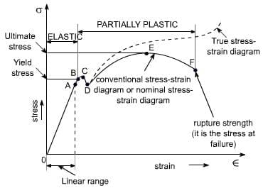
The ULS condition is computationally checked at a certain point along the behavior function of the structural scheme, located at the upper part of its elastic zone at approximately 15% lower than the elastic limit. That means that the ULS is a purely elastic condition, located on the behavior function far below the real Ultimate point, which is located deep within the plastic zone.

I can't find a reference for the approximation of 15%. We perform sectional analysis of members based on the plastic condition, and these loads are based on partial factors of safety to materials and loads. But I can't find anywhere that provides details about it remaining elastic.

 
Replies continue below

Recommended for you

On a side note this is the weirdest steel stress strain curve I've ever seen, i'd even say incorrect if it's meant to represent a real stress/strain curve for a structural steel

.... did it come from the same wiki page?

Yield_c_eat9i8_w214ff.jpg


I'd like to think any engineering student could come up with a better explanation of the ULS than the OP's wiki explanation. I've been trying the structural engineering thing for several decades and have absolutely no idea what they are actually trying to say.....
 
engtips1_lm2mrb.png


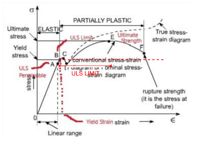
I actually always kind of viewed ULS design to be somewhere within a range of the idealized bi-linear stress strain curve, as opposed to the point just beyond yield. The point just beyond yield I imagined would be a kind of elasto-plastic range where the flanges would have surpassed the yield point, but the web section would be partly elastic still. Our sectional analysis of beams is based on a full plastic capacity section, which in my eyes would be somewhere further along the curve. Please can somebody correct me if they disagree?

Ultimately, I made this post because I thought it is very difficult to quantify exactly where we stand in terms of parts of our structure remaining in the elastic range and parts in the plastic range (but below ultimate state). In some cases members will remain elastic, but in some I believe it's possible that they enter marginally into the plastic range, but do not reach their ultimate plastic (collapse) state. The direct quote of 'upper 15%' made me question if there was a rational analysis behind this number.
 
I think there is some confusion with the word "ultimate".

"Ultimate" in the context of ULS is not the same as "Ultimate" in terms the ultimate strength of a material.

The ULS condition can occur while the material in question is in any range of stress conditions. The ULS condition can represent a steel beam which has its entire cross section fully plastic, it can represent a steel beam that has just yielded at its extreme fiber if it is not able to develop its full plastic capacity, or it can represent a stability failure where the cross section is no where near its yield limit. In a steel connections, the ULS condition could represent the actual ultimate strength of the material (fracture).
 
CANPRO said:
I think there is some confusion with the word "ultimate".

"Ultimate" in the context of ULS is not the same as "Ultimate" in terms the ultimate strength of a material.

The ULS condition can occur while the material in question is in any range of stress conditions. The ULS condition can represent a steel beam which has its entire cross section fully plastic, it can represent a steel beam that has just yielded at its extreme fiber if it is not able to develop its full plastic capacity, or it can represent a stability failure where the cross section is no where near its yield limit. In a steel connections, the ULS condition could represent the actual ultimate strength of the material (fracture).

That's the essence of my edits to the graph I think? My understanding is that under ULS the section could be in any range really from yield point to failure. Otherwise I consider it as elastic.
 
...under ULS the section could be in any range really from yield point to failure. Otherwise I consider it as elastic.

I think CANPRO's description is more accurate. The ultimate limit state can be reached well below yield, if there is a buckling failure. My understanding is, that is the essence of limit state design - capacity is calculated based on the limiting (lowest) failure condition. The 'ultimate' part indicates that it's calculated based on the expected failure level, without a factor of safety applied to the capacity, i.e. no resistance factors, distinguishing it from LRFD. It's essentially the same as what we call Load Factor Design (LFD) in the bridge design world.

Rod Smith, P.E., The artist formerly known as HotRod10
 
Some design checks are based on the ultimate tensile strength also, for example welds, bolts, net section tension checks in steel, etc.
 
I'd agree, Agent666 - whatever constitutes failure for the component under consideration, whether it be a serviceability limit or a strength limit.

Rod Smith, P.E., The artist formerly known as HotRod10
 
fracture point,

If your sketch holding true, then you will have a limiting steel stress (FLS) higher than Fy in all controlling strength criteria (equations) in the code, and your calculated member stress (FS) will be allowed to be higher than Fy, since FLS > FS > Fy, so the member is in the plastic range and deform plasticly. Do I get you right? If so, please read the definition of "plastic deformation" below, and judge yourself. You can also google the words "plastic deformation" to find results to compare the correctness of this definition.

Merriam-Webster.com said:
Definition of plastic deformation
: a permanent deformation or change in shape of a solid body without fracture under the action of a sustained force.
 
Agent666 & Rod,

I'm not familiar with welding but follows the code. Below is the only thing I think somehow explains the brittle characteristics of welding medium. In another words, I don't believe welding metal posses plastic property/behavior. The "welding forum" should be able to provide broader/concise explanations.

When molten metal is exposed to air, it absorbs oxygen and nitrogen, and becomes brittle or is otherwise adversely affected.
 
Here is a definition of ULS from UK website.

Ultimate limit state (ULS)
The ultimate limit state is the design for the safety of a structure and its users by limiting the stress that materials experience. In order to comply with engineering demands for strength and stability under design loads, ULS must be fulfilled as an established condition.

The ULS is a purely elastic condition, usually located at the upper part of its elastic zone (approximately 15% lower than the elastic limit). This is in contrast to the ultimate state (US) which involves excessive deformations approaching structural collapse, and is located deeply within the plastic zone.

If all factored bending, shear and tensile or compressive stresses are below the calculated resistances then a structure will satisfy the ULS criterion. Safety and reliability can be assumed as long as this criterion is fulfilled, since the structure will behave in the same way under repetitive loadings.

BS EN 1990 Eurocode – 'Basis of structural design' describes four ultimate limit states:
EQU: Loss of static equilibrium of the structure.
STR: Internal failure or excessive deformation of the structure.
GEO: Failure or excessive deformation of the ground.
FAT: Fatigue failure of the structure.
 
retired13 said:
fracture point,

If your sketch holding true, then you will have a limiting steel stress (FLS) higher than Fy in all controlling strength criteria (equations) in the code, and your calculated member stress (FS) will be allowed to be higher than Fy, since FLS > FS > Fy, so the member is in the plastic range and deform plasticly. Do I get you right? If so, please read the definition of "plastic deformation" below, and judge yourself. You can also google the words "plastic deformation" to find results to compare the correctness of this definition.

I don't quite follow - any chance you can try explain again for me please? We use a bi-linear idealization of the stress-strain curve, discounting any contributions from strain hardening. That's what I marked on the graph.

retired13 said:
Here is a definition of ULS from UK website.

Quote:
Ultimate limit state (ULS)
The ultimate limit state is the design for the safety of a structure and its users by limiting the stress that materials experience. In order to comply with engineering demands for strength and stability under design loads, ULS must be fulfilled as an established condition.

The ULS is a purely elastic condition, usually located at the upper part of its elastic zone (approximately 15% lower than the elastic limit). This is in contrast to the ultimate state (US) which involves excessive deformations approaching structural collapse, and is located deeply within the plastic zone.

If all factored bending, shear and tensile or compressive stresses are below the calculated resistances then a structure will satisfy the ULS criterion. Safety and reliability can be assumed as long as this criterion is fulfilled, since the structure will behave in the same way under repetitive loadings.

BS EN 1990 Eurocode – 'Basis of structural design' describes four ultimate limit states:
EQU: Loss of static equilibrium of the structure.
STR: Internal failure or excessive deformation of the structure.
GEO: Failure or excessive deformation of the ground.
FAT: Fatigue failure of the structure.

This is pulling that value of 15% again. Where does this come from? How are we able to quantify ULS design to be within 15% of the plastic limit?

CANPRO said:
I think there is some confusion with the word "ultimate".

"Ultimate" in the context of ULS is not the same as "Ultimate" in terms the ultimate strength of a material.

The ULS condition can occur while the material in question is in any range of stress conditions. The ULS condition can represent a steel beam which has its entire cross section fully plastic, it can represent a steel beam that has just yielded at its extreme fiber if it is not able to develop its full plastic capacity, or it can represent a stability failure where the cross section is no where near its yield limit. In a steel connections, the ULS condition could represent the actual ultimate strength of the material (fracture).

I like this definition!
 
What "UK website" did you quote that from, retired13?

Rod Smith, P.E., The artist formerly known as HotRod10
 
If the code allows plastic deformation/behavior, the Fult will replace wherever the Fy is in use.

My advice, don't be distracted by the arbitrarily assigned 15%, it can be 20% for shear, 10% for flexural, though I think you can find a way to compare the code permissible stress to the yield stress, and get pretty close result. Anyway, the percentage shouldn't be the focus, the concept should.
 
Upon further reading, it's seems I need to modify my comments somewhat. Most of what I read indicates that "Ultimate Limit State" (ULS) design is the 'strength' subset of "Limit States Design" (LSD), which includes the "Serviceability Limit State" (SLS) for some design philosophies, such as LRFD, and not for others, such as Ultimate Strength Design (USD) and Load Factor Design (LFD), previously used by AASHTO. LSD then, encompasses pretty much all of the commonly used design approaches except "Working Stress" (AKA "Allowable Stress") design.

Rod Smith, P.E., The artist formerly known as HotRod10
 
Rod,

I think USD is under the umbrella of ULS, I read an article somewhere, in the title it says "ULS design of reinforced concrete AS, ACI and European codes". Link
 
retired13 - the description of ULS in your link is suspiciously similar to the Wikipedia version, including the 15% number. I suspect they just copy and pasted from an earlier Wikipedia version, or maybe vice versa.

I'll have a look for a definition I like more for further discussion.

Doug Jenkins
Interactive Design Services
 
From:
"Ultimate limit state (ULS)

Design for the ULS represents a defined process that is aimed at ensuring the probability of collapse of a building (and therefore the risk to human life) is at an acceptable level. The ULS process is therefore primarily associated with consideration of large (severe), relatively rare events.

In AS/NZS 1170, compliance for the ULS for typical buildings (those with a design life of 50 years) is confirmed using a single level of load based on between a 1-in-100 and 1-in-2500-year event. This is dependent on the assigned IL and the particular environmental effect under consideration. For example, the design seismic load used for ULS checks for a typical IL2 building is based on the defined 1-in-500-year earthquake shaking. These loads are consistent with those used internationally, which is the reason they have been adopted in New Zealand. The ULS design criteria, when checked using the defined load, are set to provide the required level of confidence that the life safety objective has been met across all rare events."

This is from a New Zealand web site, but Part 1 of the referenced code is a joint Australia/New Zealand document. For specifics of earthquake design there are separate parts for Australia and New Zealand, but the general principles in Part 1 apply to both.

See the link for more background and definition of Serviceability Limit State.

Personally I think we should have three specified limit states (serviceability, strength and collapse), but that's another discussion.


Doug Jenkins
Interactive Design Services
 
Yes, our codes (NZ/AU) simply work on the principle of if we follow these detailing and design requirements, our structures will at MCE (Maximum credible Earthquake 1:2500 event) level will maintain a sufficiently low probability of collapse. In NZ we have some considerations we need to satisfy at the MCE level (primarily related to making sure thing supported on ledges like stairs and ramps don't fall off, and things like precast panels have sufficient clearances to not participate as part of the lateral system).

Some of the stuff being posted in this thread is utter rubbish, misinformed or about as incomprehensible as the original quote.

If the code allows plastic deformation/behavior, the Fult will replace wherever the Fy is in use.
This is completely wrong, plastic design is not about replacing f_y with f_u. Please don't do this. Look up the difference between the elastic and plastic section moduli for steel design for examples of the differences between elastic and plastic design.

Instead of talking about 15% this 15% that, it's the wrong terminology. The way codes work is maintaining a suitable 'target safety indice', the development of the number to use is codified in ISO standards, search google for 'ISO Bases for design of structures'. For members subject to gravity loading this might be in the range of 2.5-3.0, meaning in reality you can increase the load by this factor before something truly fails. This maintains a traditional 'safety factor' in ULS/LFRD design.

Another way to look at it is that considering capacities determined using lower characteristic material values which are factored down by strength reduction factors, being compared to upper limit loads (dead/live/snow, etc) which are also then load factored to arbitrarily increase them. On the basis of probabilistic methods we then ensure that there is a sufficiently small overlap between the distribution of reduced capacity and the load factored loading, demonstrating that there is a sufficiently low probability of the member failing under any real world loading.

This might help explain some of the concepts better than I can put it into words.
 
From ISO 2394:1998:

2.2.9 limit state: A state beyond which the structure no longer satisfies the design performance requirements.

NOTE — Limit states separate desired states (no failure) from undesired states (failure).


2.2.10 ultimate limit state: A state associated with collapse, or with other similar forms of structural failure.

NOTE — This generally corresponds to the maximum load-carrying resistance of a structure or structural element but in some cases to the maximum applicable strain or deformation.


2.2.11 serviceability limit state: A state which corresponds to conditions beyond which specified service requirements for a structure or structural element are no longer met.
 
Status
Not open for further replies.

Part and Inventory Search

Sponsor