Continue to Site

Eng-Tips is the largest engineering community on the Internet

Intelligent Work Forums for Engineering Professionals

  • Congratulations SSS148 on being selected by the Eng-Tips community for having the most helpful posts in the forums last week. Way to Go!

Question regarding Ultimate Limit State Design 12

Status
Not open for further replies.

fracture_point

Structural
Mar 7, 2019
58
I was doing some additional background reading on ULS design, and found the following quote on wikipedia:

Wikipedia said:
The ULS condition is computationally checked at a certain point along the behavior function of the structural scheme, located at the upper part of its elastic zone at approximately 15% lower than the elastic limit. That means that the ULS is a purely elastic condition, located on the behavior function far below the real Ultimate point, which is located deep within the plastic zone.

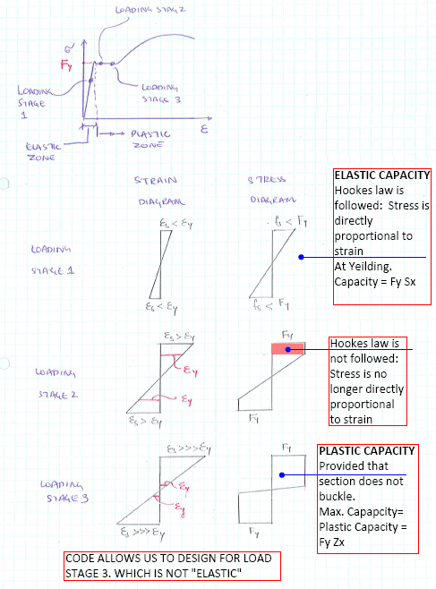
I can't find a reference for the approximation of 15%. We perform sectional analysis of members based on the plastic condition, and these loads are based on partial factors of safety to materials and loads. But I can't find anywhere that provides details about it remaining elastic.
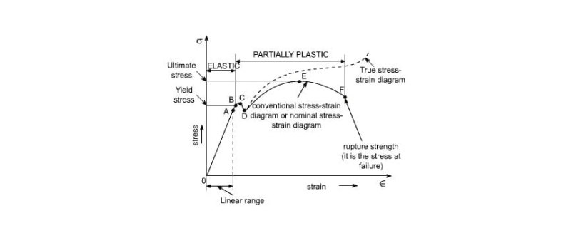

 
Replies continue below

Recommended for you

Three points:
1. The design "Ultimate Limit State" for bending is defined by strains, not stresses, and the maximum strains are far greater than the elastic strain limit. The associated stresses are derived from conservative simplifications, and are then factored down some more, but that doesn't make the analysis elastic. How can it be when large parts of the section with greatly different strains are treated as having equal stress?

2. "Limit State Design" also puts limits on stresses at the "Serviceability Limit State" with lower load factors (often but not always 1.0), and these limits ensure that the actual maximum load on the great majority of structures will result in both strains and stresses within the elastic limit. The point of ULS design is to cover the rare case where applied loads are much greater than expected, and the actual section capacity is less than assumed in the analysis.

3. The fact that ULS factors were calibrated against existing ASD limits does not mean they will always give the same results. Detail differences in the loading and in sections being analysed will often give different results, and the Limit State Design results will be more reliable because they consider the ULS, and the actual failure mechanism, and they also consider the SLS behaviour with lower loads, where strains are within the elastic limit.

Doug Jenkins
Interactive Design Services
 
retired13 said:
If I can persuade a single person to think and act elastically, I would be honored. Thanks for your thought though :)

Just in case it wasn't clear, the reason for no little pink star was that the link was to my blog, so it would have been a bit self-promotional.

I'd be interested to know what conclusions you drew from the link though.


Doug Jenkins
Interactive Design Services
 
I didn't know there were alternate definitions of elastic and plastic. Elastic means it returns to its original shape when the stress is removed; plastic means it stays in its deformed shape when the stress is removed. In the case of mild steel, the dividing line between the two is the yield point.

Rod Smith, P.E., The artist formerly known as HotRod10
 
I didn't know there were alternate definitions of elastic and plastic. Elastic means it returns to its original shape when the stress is removed; plastic means it stays in its deformed shape when the stress is removed. In the case of mild steel, the dividing line between the two is the yield point.

What was that in response to?

Doug Jenkins
Interactive Design Services
 
Perhaps I was too gentle. Retired13 is including the plastic yield plateau in his definition of elastic. This is largely why this discussion is not going anywhere.

Retired13 said:
Fy is a border line condition, I consider within and at it, it is elastic. In order to go to the next level, the stress must be greater than Fy, say Fy + 1psi (an exaggeration here). Thus the yield design method still results in an elastic structure if stability is maintained. A simple example is a beam can have both supports at yield but stable until a hinge is formed in the mid-span
 
IDS,

Internet made the world so small. If I am still practicing, that would be one of my reference regarding reinforced concrete design. Too bad, I couldn't give myself a star for finding/linking the useful information from the vast public domain though:) Nice to know that with respect.
 
BridgeSmith said:
I didn't know there were alternate definitions of elastic and plastic. Elastic means it returns to its original shape when the stress is removed; plastic means it stays in its deformed shape when the stress is removed. In the case of mild steel, the dividing line between the two is the yield point.

IDS said:
What was that in response to?

It was in response to:

Steveh49 said:
There are various definitions of 'elastic' and 'plastic' being used in this discussion. You can't all be using those words properly...

Rod Smith, P.E., The artist formerly known as HotRod10
 
steveh49 said:
Retired13 is including the plastic yield plateau in his definition of elastic.

steveh49,

Please point out the elastic yield point and plastic yield plateau in the diagram below, as I have never heard of "plastic yield" before, and would like to know/learn more. Thanks in advance.

s_p9kpm6.png
 
I still don't think the codes allow structures go plastic for places outside of the high seismic zones]

I don't know who said the above, i saw this quote and want to comment on it.

I do think that it is the intent of the code to allow us to use the plasticity of the material in regular design by ULS method.

In Working stress design method, stresses were not allowed to exceed the elastic stresses or surpass the yield point. For example, allowable stress in concrete was limited 0.45 f’c, which almost lies near the linear portion of the curve, and stress in steel was limited to Fy.

Whereas, in Ultimate limit state method, stress in concrete can reach the maximum stress f’c, and strain in steel is allowed to exceed the yield strain. Stress in steel is not increased more than Fy because of the elastic perfectly plastic idealization of stress strain curve of steel.

I consider this idealization perfectly reasonable because we do not design our beams to undergo a very large tensile strain such that it reaches the strain-hardening regime. However, if someone is interested in taking into account the strain hardening effect of high strength steel, various bi and tri linear models have been proposed in the research works in past several years.

In addition, serviceability of building designed by working stress method is so much better than ultimate limit state method. Because in working stress, frame sections were designed so that the stresses remain less than the elastic stresses which results in large cross-sections and small displacements. Compare to this in ULS method, frame sections are allowed to deform past their yield points.


Euphoria is when you learn something new.
 
IDS,

In your blog, I am confused with the statement below, can you clarify? Thanks.

The two BS codes are limited to a concrete cube strength of 65 MPa, which is equivalent to a cube strength of a little over 50 MPa. The other codes have modifications to the concrete stress block for higher strength grades, to account for its reduced ductility.
 
Retired13, in answer to your question on the yield plateau, as a number of people have stated that stress strain curve is not representative of a real stress strain curve for structural steel. One reason is it doesn't contain a defined yield plateau. I think someone mentioned earlier that this plateau is maybe 15 times the yield strain.

This is what I'd expect a real structural steel stress strain curve from testing to actually look like:-

images_d6jyiv.jpg


In addition, serviceability of building designed by working stress method is so much better than ultimate limit state method. Because in working stress, frame sections were designed so that the stresses remain less than the elastic stresses which results in large cross-sections and small displacements. Compare to this in ULS method, frame sections are allowed to deform past their yield points.

This is simply not true. There is another limit state called the serviceability limit state under which the serviceability of a structure is checked (deflections, fatigue, durability, vibration, etc) The intent of limit state design is that under the serviceability load cases (SLS) that structures remain in the elastic stress range and hence remain serviceable. This has nothing to do with ULS which is separate limit state.
 
Interesting diagram. I wonder the deformation in that plateau is recoverable or stay permanent.

Yield Plateau

p_cxzwee.png
 
Agent666 said:
This is simply not true. There is another limit state called the serviceability limit state under which the serviceability of a structure is checked

May be you didn’t understand my point. I didn’t say the beam designed by ULS are not checked for their serviceability.

I was comparing the serviceability of old method (Working stress) and new method (Ultimate limit state).
I think you can well imagine the magnitude of deflection in a design method in which stresses were not allowed to exceed their elastic stresses VS the design method in which members are allowed to crack at their ultiamate life but are supposed to be within well defined deflection limits in their service life.

It’s obvious to me the serviceability of the old method will be better than the new ULS method. However, it will not be an economical option for sure.


Euphoria is when you learn something new.
 
Simeone answered the question on importance of the yield plateau in structural engineering, the answer may not be written perfectly, but I think it makes sense. Please read on. Note he use "yield area" instead of yield plateau.

"I´d rather say yielding stretch is a feature, a characteristic of most of metal material.

Most of structural assumptions( at least for civil engineering purposes) take in account yielding point rather than rupture point.

Because most of structural calculations are made in the dominion of elastic field. Considering the mentioned graphic of Stress X Strain, beyond the yielding part, steel( or other metal) don´t behaves on elastic way, but on plastic mode. The yielding point it´s somehow safer to calculations, because close to such "yielding area" the strains grow without additional efforts, what it is a warning about complete "burst"( or rupture) is close.

More...most of calculations are made inside the "elastic area" which follows Hook´s Law. At elastic area, strain can be recovered if load is withdrawn. At the plastic area strains are permanent( it is the anticipation of the rupture).

I wish I could be understood ."
 
I am going to make my closing call to end my journey on this subject.

Maybe caused by my poor writing skill, thus led to misunderstandings on my stance, that stated below:
- For typical structural steel, elastic behavior stops at "yield, Fy". Beyond the yield point, plastic behavior starts.
The current code specified structural resistance capacity calculations are well remain in the elastic range, thus the use of Fy in the equations. I don't know where is the future heading toward, but at this moment of time, none of the codes allows the venture into the plastic range (except the high seismic zones mentioned before), whether through a ladder/escalator up or down as shown on the diagrams above this thread.

It is interesting to know so many different opinions on this subject though.
 
retired13 said:
The current code specified structural resistance capacity calculations are well remain in the elastic range, thus the use of Fy in the equations.

ok.. This just made me sad that's why I've gone to the following trouble.

image_ibxkdm.png


Euphoria is when you learn something new.
 
retired13: "none of the codes allows the venture into the plastic range"
If not into it, very close to it. With rectangular sections the shape factor Mp/Me is 1.5. With a low load factor, DL being 1.25 and material factor of 0.9... you may be into the plastic range.

Blackstar123:
Once the section is unloaded, with the residual stresses, Hooke's law is applicable up to the latest 'plastic load'.

With rolled sections you are not likely in the plastic range for service loading with a shape factor of about 1.15 for rolled sections and material factor of 0.9 and DL factor of 1.25.

This has been a great thread... one of the more interesting ones...

Dik
 
Blackstar,

It is transition from the proportional point to the yield point, that can be called non-linear elastic zone, which is located between points A & B on the first stress-strain curve I posted on 21 Jan 20 23:04 (first post down from the OP) I don't think Hooke's Law is applicable after the proportional point.
 
Dik,

The case you described could be fall in the risk category with DCR > 1. I recommend the video (NASCC Steel Conference) originally provided by Agent666, and linked here. Link
 
Thanks for the link... I'll look at it later today... this has been a really 'fun' thread.

Dik
 
Status
Not open for further replies.

Part and Inventory Search

Sponsor