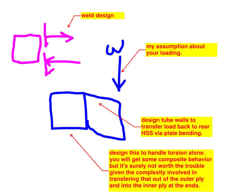
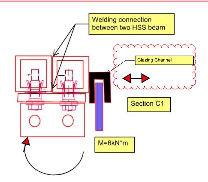
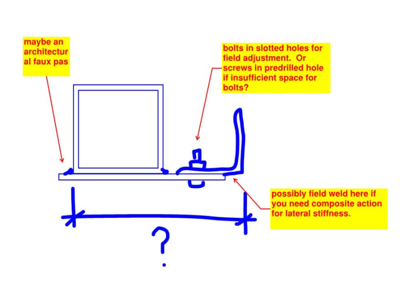
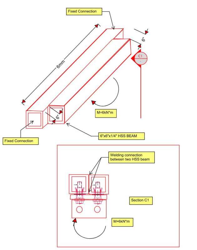
I am currently being asked to design a double HSS that is subject to torsion along its length. The HSS at the back is supported by the concrete wall at its end (torsion resisted), and the front HSS, which I am designing, is planned to be attached to the front face of the back HSS with either bolts (at specified intervals) or welds, and both are subject to torsion.
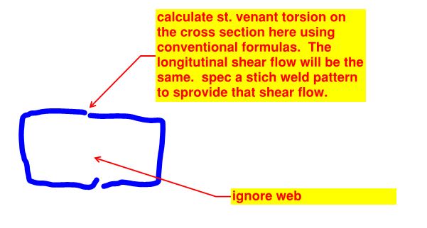
My question is, how do I check the torsion in this situation where there are two HSS sections side by side? Should I consider these two HSS sections as a composite section? If so, what formulas should I use to check the welding (or bolt connections) to ensure these two HSS sections act as a composite in resisting torsion?
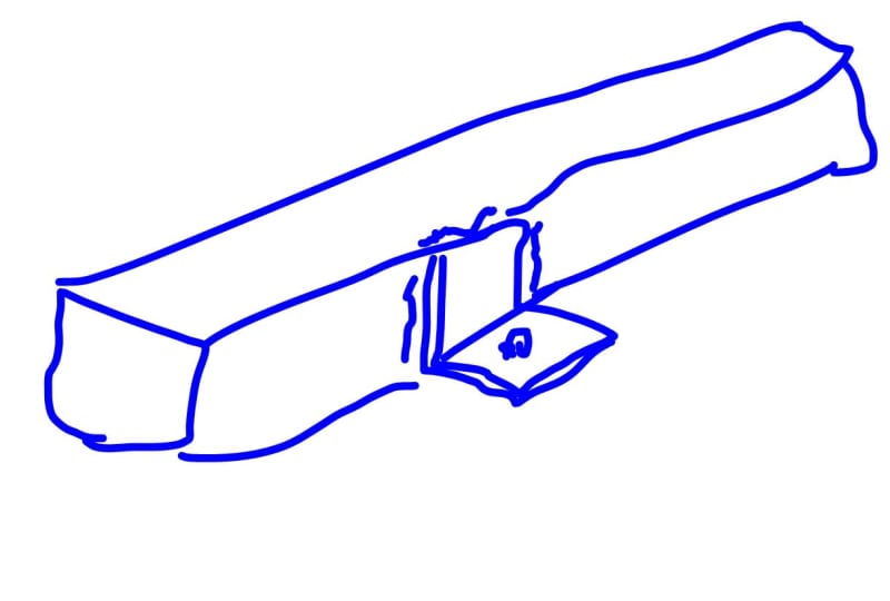
Additionally, the front HSS is not supported at its end and will be about 6 inches shorter than the back HSS. In this case, there is a 6-inch span where only the back HSS is present without being stiffened by the front HSS. I believe this span area also needs to be checked as a single HSS, as its torsion strength will be lower than that of the composite section. Am I correct?
My question is, how do I check the torsion in this situation where there are two HSS sections side by side? Should I consider these two HSS sections as a composite section? If so, what formulas should I use to check the welding (or bolt connections) to ensure these two HSS sections act as a composite in resisting torsion?
Additionally, the front HSS is not supported at its end and will be about 6 inches shorter than the back HSS. In this case, there is a 6-inch span where only the back HSS is present without being stiffened by the front HSS. I believe this span area also needs to be checked as a single HSS, as its torsion strength will be lower than that of the composite section. Am I correct?