Eng-Tips is the largest engineering community on the Internet

Intelligent Work Forums for Engineering Professionals

Questionable true position callout - 2

Status
Not open for further replies.

weavedreamer

Automotive
Aug 1, 2007
279
0
0
US
Interpretation_2_z9wlmd.jpg

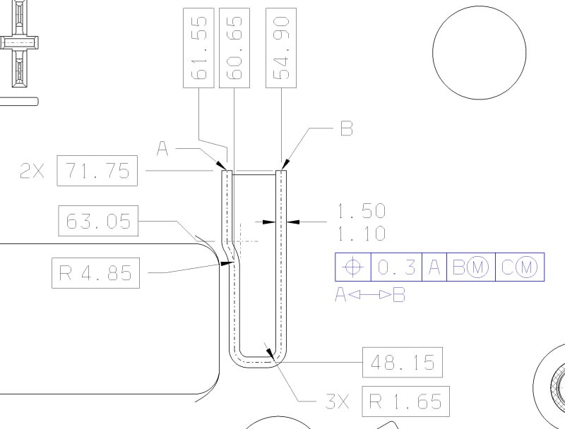
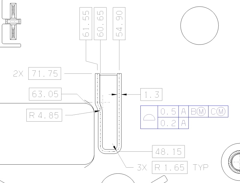
Will this control the width of a rib or an groove along a basic path identified from end A to end B while ensuring the center of the rib or groove is within the prescribed tolerance zone?
An extension of principle derived from illustration shown in ASME Y14.5-2009 Fig. 7-29.
The datums, while not shown, have A as if the plane of the view is resting on it, while B and C are two holes perpendicular to A.
The position anywhere along the rib to be the feature of size taken perpendicularly normal to the centerline at any point along it.

Same question, different example.
 
Replies continue below

Recommended for you

I think the below quote from your cited thread provides a succinct answer.

axym said:
https://www.eng-tips.com/viewthread.cfm?qid=454023,[/URL] 23 May 19 20:39]Y14.5 doesn't currently support position RFS for curved slots. There is no actual mating envelope defined, and hence no "resolved geometry" to be contained within a tolerance zone. So if the intent is to control the radial location of the slot "centerline", there really isn't a direct way to do that. There are only tools to control the surface.

A groove of the shape shown in your example would be a instead of a simple curved slot, a "complex" curved slot. Evan follows up with a description of an extension of concept utilizing EACH ELEMENT - you're on your own trying to implement something like that especially since your example is not a single, simple slot but a collection of features creating a "complex" slot as I noted.

If you can hold the entire profile to a single, fixed tolerance, profile I think is your friend here - possibly with a composite/MSS refinement to allow float relative to the DRF. If expansion/contraction of the profile is required then Y14.5-2018 is needed which details the use of a dynamic profile modifier.
 
Just a minor note - your FCF is floating, this should be connected to a leader line pointed at the surface and judging by the fact that you want to control the entire profile together the "all around" symbol is probably appropriate.
 
Status
Not open for further replies.
Back
Top