Eng-Tips is the largest engineering community on the Internet

Intelligent Work Forums for Engineering Professionals

Questions and help regarding Automatic Stabilization 1

Status
Not open for further replies.

justAnEngineer95

Mechanical
Jan 31, 2022
10
0
0
DK
Hi everyone,

If you have any experience with using automatic stabilization I would like you help with clarifying something.
Is it possible to fix the damping factor used? I have noticed that the it is still possible for it to increase during each increment, which causes the dissipated energy to exceed 5% of the total strain energy in the model as the simulation goes on until it ultimately converges.
eng-tip%C3%A5s_abuwuw.png


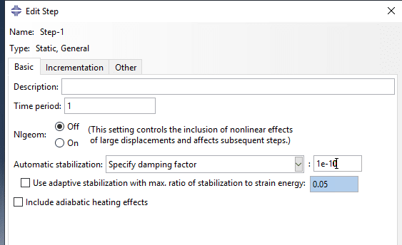
This was the behavior I expected from "specify dissipated energy fraction" as I have encountered here that the ratio may adjust itself, but not from "specify damping factor", where I expected that the damping factor would remain constant.
I have turned off the "use adaptive stablization with max ratio of strain energy" as I discovered that this was only a target value that still could get exceeded if Abaqus deemed it necessary.

Is it possible in Abaqus to cap the damping factor?

BR.
 
Replies continue below

Recommended for you

If all the types of automatic stabilization (with specified dissipated energy fraction or with specified damping factor and with or without adaptive stabilization and with different values for each setting) result in unacceptable growth of viscous damping energy in your case then it's likely that you may have to abandon the use of automatic stabilization in favor of other approaches that aid convergence. There are many ways to achieve it, depending on the nature of your particular scenario.

I will just add that it is advised to check both ALLSD vs ALLIE and/or ALLWK as well as viscous forces (VF) when verifying the influence of automatic stabilization on the results.
 
Hi,

My problem is related to the modelling of zero-thickness cohesive elements in a scarf joint.
My original plan was to use viscous regularization, but this causes the cohesive interface tractions to exceed the specified onset-traction values.
This is also unphysical and sort of throws a monkey wrench in a potential traction analysis.

That is why I turned to automatic stabilization instead, but noted that in most instances the ALLSD/ALLIE exceeds the 5% threshold.
If possible I would like to avoid the usage of Abaqus Explicit.
 
Hi NRP99,

I will take a look at that.
Are there anything I should be aware of, i.e. material densities of the zero-thickness cohesive elements, time increment etc.?

With automatic stabilization, we would check to see ALLSD/ALLSE exceeded 2%-5%. Are there similar checks for implicit dynamic analysis?
 
For cohesive elements it's usually advised to use viscous regularization to aid convergence but you said that it causes different problems. You could also try specifying nondefault solution controls.

Dynamic implicit analysis with quasi-static application type involves numerical damping to help with instabilities. Of course you can check the kinetic energy to make sure that the solution can be considered as static.
 
OK here is my procedure so far. I will update you when the simulation is completed.

1) Added densitities for all my materials, carbon UD, carbon biax, glass biax by converting kg/m^3 to tonne/mm^3 by factor 10^-12, since I run everything in MPa, mm etc.
2) Performed an Eigenvalue analysis to compute the 1st natural period.
3) Created a dynamic/implicit step with a quasi-static approach, where I have inputed 10*natural period as the total time period.
4) Applied a displacement-controlled linearly ramped boundary condition on one end of my scarf joint. This is created in the dynamic step.
5) Fixed the left side of the scarf joint, which is created in the initial step. (Sort of similar to a cantilever beam)

Once the analysis has run, I will try to check:
- Force-displacement curve of the displacement-controlled BC, that is U1 and RF1.
- ALLKE/ALLIE < 5%.

 
UPDATE:

DEBUG_model_paj6yv.png


(Model illustration - cohesive elements are placed in the scarf joint interface, while the rest are quadratic solid elements.)

ALLKEvsALLIE_dfslwr.png

(ALLKE/ALLIE)

It seems that I encounter a similar problem as when I use automatic stabilization.
The kinetic energy continues to increase beyond 5% as the simulation goes on until it converges. The critical frame number at which this occurs is 128.
However, for the dynamic implicit analysis there is an offshoot branch in the curve - the part after time 2.2.

Implict_FvD_b9blq3.png


The force-displacement curve also looks similar to the static general step analysis, but it now includes a negative part which is a bit weird.

TractionDip1_ebivez.png
TractionDip2_vofj5j.png


I want to conclude that the analysis is somewhat valid up until we hit frame no. 128, and then unstable crack propagation occurs. What then happens here after is unknown.
What is really interesting when looking at the tractions is that they sort of "dive" long before frame no. 128. This dive occurs around frame 20 to 30 where damage slowly starts propagate. Damage is observed by looking at the scalar damage variable SDEG.
It is hard for me to conclude whether or not this is something unphysical that occurs due to the numerical damping induced from the dynamic implicit analysis, or it is simply a stress-redistribution due to increased in damage, since the kinetic energy/ALLIE is still below 5% at this point.
A similar thing observation happens when I just use automatic stabilization, although the traction dip occurs before damage propagates. It seems that this may occur due to a rapid increase in the damping used, while in the implicit dynamic analysis, the numerical damping is a bit more spread out over the increments, so that the SDEG and tractions plot follow each other more nicely.

Anyone care to comment on the final observation regarding tractions?
 
Status
Not open for further replies.
Back
Top