Eng-Tips is the largest engineering community on the Internet

Intelligent Work Forums for Engineering Professionals

"Compression" steel actually in tension - justifiable for capacity?

Status
Not open for further replies.

Gallig3r

Structural
Aug 9, 2023
11
0
0
US
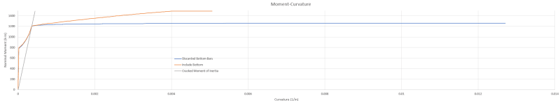
I'm evaluating an existing condition, with a very lightly reinforced 2-way slab system.

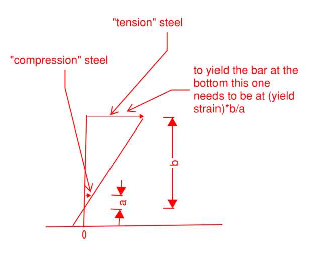
We were trying to eek out capacity by considering compression steel at a support, but noticed that the neutral axis was very small. The "compression" steel was actually in tension at the ultimate limit state. In fact, in many sections we evaluated the bottom steel was even yielding in tension!

Yes, the bottom bar is fully anchored and developed at face of supports. However, I have some heartburn about developing yield (in tension) from the other side of the critical section, an issue that isn't present for the top bars (as sketched in the attached).

Consider the moment diagram of a fixed-fixed span. The negative moment decreases quadratically from peak negative moment at the face of support. The point at which the cracking moment is exceeded is qualitatively not that far away from the face of support. So there is (qualitatively) not much length to develop the tension force in the bar.

Thoughts? Is there something we're missing? (such as considering rebar slip?).

Cross section properties for those who like to check math:

180" width of 8" slab, 6ksi concrete
10#5 top bars (d=6.875")
15#5 bottom bars (d'=1.125")
 
 https://files.engineering.com/getfile.aspx?folder=3c9dfd20-9b30-4c9e-ba55-a8f2c68b7bae&file=Section_Mechanics.png
Replies continue below

Recommended for you

You say you're using a two way slab but you're only taking into account reinforcement in one way from how I am reading your question. You're also calling out that you're designing with a 15' width. What is the length of the slab in the other direction? If it is more of a square shape then you definitely are being conservative by only analyzing in one direction.
 
I did a deep dive into this a couple of years back but I can't remember if there was a code cutoff distance where you had to be a certain distance past the compression block.

Regardless, there are theoretical and practical issues that make it a generally bad idea.

It's going to be so sensitive to bar placement that even if you wanted to theoretically count it I bet you'll lose the capacity if you build in an allowance for construction tolerance. If your moment arm from the compression block is only an inch an a half, then a placement tolerance of half an inch or the layers being a different order than you expected could take a large fraction of your capacity away.

You're also going to have really big crack widths and your far face bars are going to have to strain a long way past yield to yield your compression face bars. Your tension face will be at several times the yield strain, probably.

I once did a very aggressive check of a T beam where I pulled slab bottom bars in as well as side bars, even though they were well into the top half of the beam. However, this was a high factor of safety situation, so everything was conventional at service level and those aggressive things only happened as you started getting into the FOS of 2+ range. I couldn't have made servicability considerations work otherwise.

If you were to try to justify this, because it's an existing condition, you'd have to look really hard at what happens in the service case and you'd definitely need to do the full strain analysis and things that normally aren't really necessary. It also depends on whether you're using it to get from FOS of 1.4 to FOS of 1.5 or if you're going from 0.9 to 1.1 or something. Like, how comfortable are you without accounting for that reinforcement.

I heavily lean towards this being a bad idea even if the math seems to work unless it's effectively bonus capacity.

Also, are you even a 'fixed' end moment once you look at the stiffness of that after the main tension bars yield? It feels like you're probably into hinge territory with the amount of deflection you'll get when you yield the 'compression' face
 
I think TLHS brings up a great point, why are you examining the slab? Are you wanting to put a new piece of equipment on the slab? Are you redefining the occupancy and live load? What is the required factor of safety going to be for you?
 
TLHS “ You're also going to have really big crack widths and your far face bars are going to have to strain a long way past yield to yield your compression face bars. Your tension face will be at several times the yield strain, probably.”

I would actually expect the opposite if the “compression” side bars are actually in tension then to satisfy section equilibrium the neutral axis would be lower and actually reduce the extreme tension strain and you’d reach the anticipated capacity at less curvature. So you want to make sure the far face bars yield so the section remains tension controlled.

There are likely some adverse side effects on the shear resistance if relying on the bottom bars as tensions bars especially so if they work out to be more T than the top bars.
 
I agree with Tom, but as a point for conversation, what is the midspan capacity like? If you go to a hinge here can moment redistribute assuming a pinned or partially fixed end?

Is what you're looking at a potential collapse mechanism, or is there somewhere for the load to go?
 
Celt, in normal reinforcing patterns that would be true. In this case the bars are so far apart that the effects of the bar distances will be much more significant than the shifting of the neutral axis, unless I'm misunderstanding the mechanics of this admittidly unusual situation.

If you're just yielding the one layer of bar then your tension face strain is basically just the yield strain of the rebar. Now you need to yield both, though, so your bar just slightly past the compression zone has to yield. To maintain strain compatibility your far bar now needs to go well past yield strain and your crack sizes open way up.

Realistically there's probably some amount of plastic deformation 'plane sections not remaining plane' stuff, but that breaks things if you start going down that road too far.

Screenshot_2024-03-01_162320_khl6r3.png


This is also why your stiffness falls off a cliff once you hit yield on your main tension bars. Those bars turn into a hinge and now your effective section for loads past that point is just the compression block and the 'compression' steel in tension.
 
This is surely an odd case especially so since there are more “compression” bars than top face bars. My quick napkin calc the extreme tension steel strain gets reduced by 1/3ish if considering the near face bars as tension reinf.

et = 0.028 with bottom face bars in tension (a=0.502 in)
et = 0.074 w/o consideration of the bottom bars (a=0.203 in)

a = whitney block depth
 
Yes, this is an odd case. More bottom than top bars over support. And before the calculations get too precise, consider that bars are often not placed at the exact depth assumed.
 
Fair enough, Celt. I didn't do the math and it looks like it may be more strained as a starting point that I figured. In that case the effects I'm talking about potentially don't become significant.
 
If you reduce down to a per foot basis the additional capacity works out to less than 1 ft-kip/ft and it barely satisfies minimum flexural steel requirements.

I imagine there are other adverse effects to using a layer of steel for tension that is far away from the tension face but would need to research more.

 
Thanks for discussion all.

Forgive me, I'm new to using the site, although I stumble across it frequently when researching random topics. I think I am quoting properly....

WesternJeb said:
You say you're using a two way slab but you're only taking into account reinforcement in one way from how I am reading your question.

15' is the column strip width for sample section, although similar situations occur. Demand was taken by using a section cut to integrate stresses from a linear elastic FEA (RamConcePT specifically). We are indeed using moment redistribution to help the demand side where possible. However, the capacity side is the main question.

Tomfh said:
The top will be long past failure by the time those bottom bars kick in.

We got more or less same strains at nominal as Celt83 calculated; the top bars can handle more member rotation before rupture.

TLHS said:
Realistically there's probably some amount of plastic deformation 'plane sections not remaining plane' stuf

Exactly, we were wondering if rebar slippage (inherently breaking "plane sections plane" assumption) would justify a longer length of development compared to the green development stresses I sketched. Alas, getting too theoretical without examples/precedent...

TLHS said:
I can't remember if there was a code cutoff distance where you had to be a certain distance past the compression block.

I was curious if software might have such a limit implemented. Will check others, but SP Column did not, FWIW(don't reduce when <1%). It was fully happy to state the flexural capacity based on the bottom bars reaching yield. When evaluating sectional capacity in a vacuum, I wouldn't disagree. However, I'm not convinced the general shape of a traditional parabolic wL[sup]2[/sup]/# moment diagram would justify the bottom bars developing yield at the support cross section.


Nothing to add to the discussion except that I ran the numbers and found neutral axis and stress block depths identical to those calculated by Celt83.

Summary with bottom bars:
c = 0.67", a = 0.50", phi*Mn = 7,360 ft-lb / ft

Summary without bottom bars:
c = 0.27", a = 0.20", phi*Mn = 6,300 ft-lb / ft
 
In RAPT, we have ignored the steel near the compression face as tension reinforcement for several years.

With modern shear design methods like MCFT, you should only consider reinforcing in the tension half as being in tension.
 
rapt said:
With modern shear design methods like MCFT, you should only consider reinforcing in the tension half as being in tension.

I am not overly familiar with MCFT, so this made for some light afternoon reading :) Thanks for sharing this model/ framework.

Although I have my own reservations about utilizing this rebar, I'm not sure I fully understand the theoretical concern from the lens of MCFT - could you help me out or walk me through your point?

Is it because if we assume the bottom bar is yielding in tension, the necessary stress trajectories would illustrate a concentration of vertical shear stresses between compression block and that bottom layer of steel (rather than more evenly distributed across the entire depth of slab?)

Appreciate the insight/ help!


Unlike the others, I don't have a specific reason to discount "compression" bars in tension for lightly reinforced beams and slabs. So I do the full strain analysis and include the capacity -- knowing it's generally a 10% boost at best.

This is with an additional check on extreme tensile reinforcement strain (against ductility limits), members proportioned such that shear utilizations are very low, where larger crack sizes at the extreme tension fiber are tolerable (hidden by finishes, non-corrosive environment), and in non-seismic scenarios.

I'd also love to hear RAPT's consideration of MCFT, as I'm also not familiar.
 
why do we think there would be more flexural cracking?

To me this moves closer to an over-reinforced section which would mean less overall curvature, leading to less extreme tension strain and overall less cracking. A pitfall becomes the potential hit to ductility and less warning before failure.
 
Lomarandil said:
Unlike the others, I don't have a specific reason to discount "compression" bars in tension for lightly reinforced beams and slabs. So I do the full strain analysis and include the capacity -- knowing it's generally a 10% boost at best.

Do you have concerns about being able to develop the stress in that bottom bar, after reviewing the sketch/ discussion in the post? If you do a strain analysis on a cross section just a few inches away from the support (assuming typical span, moment is parabolic distribution), you may find that bottom bar is in compression. I'm concerned the quick transition from compression to full yield in tension is not justifiable. I recognize it may be possible to have a span loading condition that would justify counting on this bottom bar in tension (lets say a middle span of a long-short-long span configuration), where the span is primarily in "negative" flexure.


Celt83 said:
why do we think there would be more flexural cracking?
This particular project that I am evaluating has very low reinforcement ratios in my experience and relatively large spacing of tension reinforcement. I'm assuming that's what people are addressing, as opposed to discussing consequences of utilizing this in a new design (I would strongly discourage counting on compression steel as tension in new design....)

Celt83 said:
The pitfall becomes the potential hit to ductility and less warning before failure.
With flexural sections containing multiple layers of tension reinforcement, the portion of the moment-curvature diagram isn't so flat after the outermost layer yields. It only becomes flat after the last layer yields. However, I would say either case generally has ductile behavior as it is "flat" enough relative to elastic behavior. Plots is based on excel spreadsheet that numerically iterates each data point to find neutral axis.

Moment_Curve_g4pnne.png


After generating this plot, I realize moment redistribution on the demand side is potentially non-conservative if we are counting on the higher capacity from compression steel in tension - there is relatively reduced amount of rotation deformation after the bottom bars yield, so that is something we'd need to potentially consider.
 
I didn't realize the picture would end up so compressed.

blue plot is the moment-curvature diagram when ignoring bottom bars.

orange plot is moment-curvature diagram when considering bottom bars. They diverge after the top bars reach yield. The orange plot increases in nominal moment... until after sufficient deformation the second layer (bottom rebar) yields.

I also plotted a gray line which is if you were to ignore elastic section properties and cracking/tension stiffeneing (I gross and I effective) and instead just consider I cracked.
 
Status
Not open for further replies.
Back
Top