Continue to Site

Eng-Tips is the largest engineering community on the Internet

Intelligent Work Forums for Engineering Professionals

  • Congratulations SDETERS on being selected by the Eng-Tips community for having the most helpful posts in the forums last week. Way to Go!

"ISO 6403:1988 Hydraulic fluid power — Valves controlling flow and pressure — Test methods&quot

Status
Not open for further replies.

PNachtwey

Electrical
Oct 9, 2004
778
The abstract.
This document cost money and I don't know if it covers what I am interested in. The title is not very specific.
I need to know if it covers hydraulic servo valve testing for generating Bode plots.
I am hoping someone would know. Otherwise I will need to do more digging or just buy the document and take a chance.
I see nothing in the table of contents that mentions servo valves or Bode plots. I would think these topics would be in the table of contents if this information was covered.
I do see topics such as pressure reducing valves and pressure relief valve but that is not what I am interested in.
Why mention pressure pressure reducing valves and pressure relief valves and not servo valves unless servo valves are not covered by this document.

If there is no specification for testing hydraulic servo valves then the servo valve manufacturers can make up any data or specifications they want and the user won't know the difference.

I am going to write an article about testing servo valves for "Hydraulics and Pneumatics" magazine. I/we have recently got involved with servo valve testing. However, I have issues how servo valves are tested from the standpoint of motion control needs. Unless I am wrong, I have come across a big problem when it comes to rating valves that are use for servo control.

Is there a standard for testing servo valves so company A's servo valve can be compared with company B's servo.
So the questions I have are "are the ISO tests, if any, flawed?". This would affect how engineers should interpret the data they are given by the manufacturers.


Peter Nachtwey
Delta Computer Systems
IFPE Hall of Fame Member
 
Replies continue below

Recommended for you

I think this is what you are looking for.

PREVIOUSLY
WITHDRAWN
ISO 6404:1985 Hydraulic fluid power — Servovalves — Test methods
>
NOW
WITHDRAWN
ISO 10770-2:1998 Hydraulic fluid power — Electrically modulated hydraulic control valves — Part 2: Test methods for three-way directional flow control valves
>
REVISED BY
PUBLISHED
ISO 10770-2:2012 Hydraulics and pneumatics - Electrically controlled directional valves for hydraulics - Part 2: Test methods for three-way directional valve for flow control.

ISO 10770-2:2012 describes methods for determining the performance characteristics of electrically modulated hydraulic three-port directional flow-control valves.
This type of electrohydraulic valve controls the direction and amount of hydraulic flow in a hydraulic system.

Best Regards A

“Logic will get you from A to Z; imagination will get you everywhere.“
Albert Einstein
 
Looking at BS 4062-2, which claims to be a direct National Implementation of ISO 6403-1988:

The scope specifically excludes proportional control valves, referring out to ISO 6404 for electrohydraulic servovalves - which, as Anna points out, has now been superseded by ISO 10770-2:2012

Tests for solenoid-controlled two-stage directional control valves are included. Under the heading of Transient Characteristics, the standard specifies a step response test for these, measuring the delay time before the spool starts to move and then the response time it takes to travel - performed in both directions. It doesn't derive a frequency response - which appears sensible since it only applies to bang-bang valves.

On the other hand, Section 8.2.5 of ISO 10770-2:2012 does invest a couple of pages in telling you how to derive a Bode plot for a servo valve.

A.

 
Thanks guys.
Now I am pretty sure I will buy the right specification and not waste money on a wrong one.
My company does not make valves but we do get involved with the testing of servo valves.
So far it seems that the Bode plots are showing the velocity response to a sinusoidal control signal.
However, it is the position of the valve spool that controls the flow and the amplitude of the position response will decrease as a function of increasing frequency.
My point is that a Bode plot may show a flat response at 0 db out to 200 Hz for the velocity but the amplitude of the position sine waves will differ by a factor of 2 and it is the position that is important.


Peter Nachtwey
Delta Computer Systems
IFPE Hall of Fame Member
 
And girls ;-)

I am not shore what this Bode plot actually is, most proportional /servo valves have curves in pressure in relation to command value and pressure in relation to flow, that is at least what is important for me as a user.

I hope you can find what you are looking for.

Best Regards Anna

“Logic will get you from A to Z; imagination will get you everywhere.“
Albert Einstein
 
For Anna,
A Bode plot is a plot of the valves magnitude/gain and phase as a function of frequency.
The Bode plot tells the designer if the valve would move fast enough for the application.
Here is an article written by me.
Notice that in the third paragraph I write
"The amplitude and phase of the valve spool is compared to the amplitude and phase of the valve’s input. "
This is not specific enough. Is it the amplitude of the position response or velocity response.
It makes a huge difference in how one uses the data from the plot.

What good is information if you don't know how to use it?

I may need to update that article.


Peter Nachtwey
Delta Computer Systems
IFPE Hall of Fame Member
 
I did look at the internet to see what Bode plots where, and realized I hade not seen any in the dokumentation on the proportional valves I have been looking at lately, hence my comment.

My work doesn't include designing hydraulic systems.
Sometimes it includes changing proportional valves or servovalvs for pressure or flow, but in that situation the choices are rather limited since it need to fit mechanically and electrically with the rest of the equipment.

The valves we have in our machines are like three generations, simpel valves with proportional current amplifier boards without
feedback or more programmable boards with feedback or servo valves with internal feedback.
The input is always DCV and there is the possibility to put a oscillating harmonics on the input to make the valve cone vibrate to make it easier start moving it.
In none of our applications time is particularly critical, the output pressure is though and to some extent the flow that goes with it.
For example we need a valve that can be regulated between 0-315 bars with a adekvat flow at as low pressure as possible, if the flow is to high at 315 bars that is handled outside the valve, usually the valve is regulated on the outgoing pressure, the feedback from the cone is usually only a check that the valve is in working order not used for regulation since the input value and pressure isn't linear.

I do realize that for other applications and new designs more information and knowledge is always a positiv, I hope your work goes well and that you find the information that you are looking for.

Best Regards Anna

“Logic will get you from A to Z; imagination will get you everywhere.“
Albert Einstein
 
That might be the difference then.
Our prop/servo valves are mostly for pressure and the few we have for motion(flow) the actual speed that is generated isn't critical and don't need to be very specific and accurate for the function of the machine or the quality of the product.

There are surly other applications where this is very important.

BR A

“Logic will get you from A to Z; imagination will get you everywhere.“
Albert Einstein
 
Anna, depending on where you are in the world, the word "servo" is sometimes used to describe basic pilot control as well as proper servo valves used for control systems. That can cause some confusion.
 
Yes I am aware of that, it is a bit of a language barrier sometimes. :)

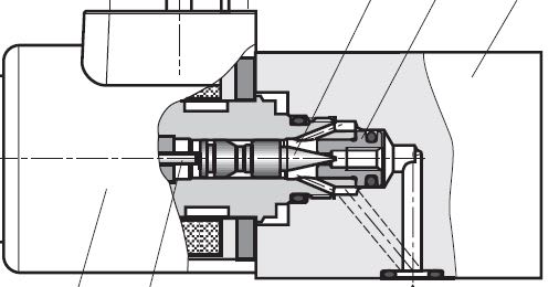
This is what I call a proportional valve, command value 0 to 10 V or 4 to 20 mA quite simpel (no fuss) ;-)

a_uxex2p.jpg


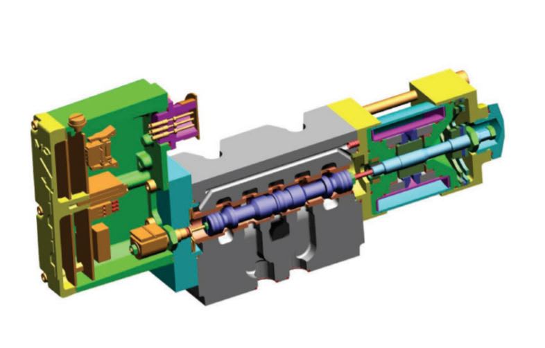
And this is the one we have that is called a servo proportional valve and it has a motor and it is a bit more to this one.

a_mtzura.jpg


None of them comes with more the command value contra flow or pressure curves or with flow contra pressure drop curves.

I am not saying this to be critical in anyway it's just a fact for these two valves.

BR A


“Logic will get you from A to Z; imagination will get you everywhere.“
Albert Einstein
 
Status
Not open for further replies.

Part and Inventory Search

Sponsor