Continue to Site

Eng-Tips is the largest engineering community on the Internet

Intelligent Work Forums for Engineering Professionals

  • Congratulations GregLocock on being selected by the Eng-Tips community for having the most helpful posts in the forums last week. Way to Go!

"kicking" a slip on flange 2

Status
Not open for further replies.

CGarfield

Industrial
Dec 15, 2008
11
Good day;
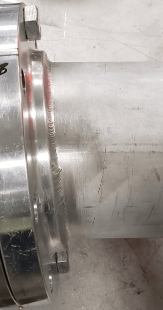
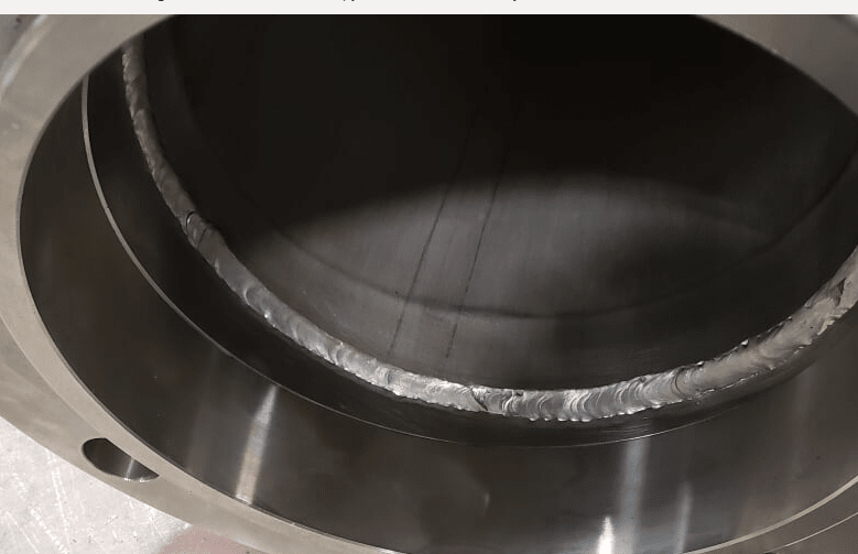
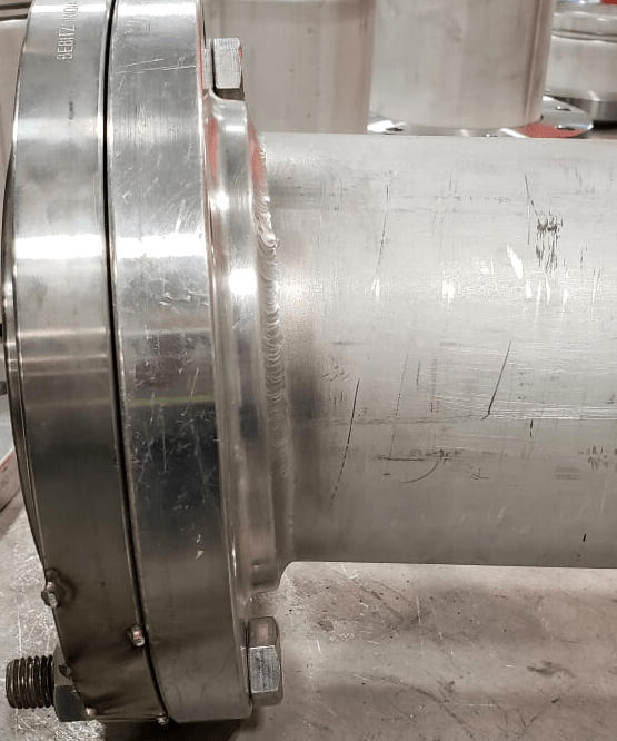
This question has come up a few times in my world, and I'm hoping someone can point me in the right direction. I'm sure we've all seen pipe spools where someone has cheated while installing a slip on flange. The flange is "kicked" a bit to change the direction of a pipe. I've seen it done a lot, but I'm not sure if it is permissible by code. The spool I was shown today is probably one of the most extreme examples of a kicked flange that I've ever seen.

I've read a lot about the placement of the slip on flange in relation to the end of the pipe (set back for the weld). We do a lot of work in ASME B31.1 and B31.3, and these codes don't tell you the amount of setback to use (unlike AWWA where they are very specific about where to position the slip on flange in relation to the end of the pipe). I don't believe either ASME B31.1 or B31.3 address the kicking of a flange while welding it.

Material is 316L SS
Code is ASME B31.3
Flanges are B16.5 slip on (class 150)

The photos below show a spool that came in to our shop (not fabricated by us). It was field fabricated by one of our clients. The spool came back to repair an unrelated issue flagged by non-destructive testing of the welds. Our concern is that if we fix the issue and return to our client, the engineer will look at it and say the flange is not acceptable. I hear a lot of "we do it all time", but as we all know, that doesn't make it right. If this is a code issue, I'd like to notify our client right away so that we have the opportunity to fix it before it is returned to site. I know why they did it. It's a really ugly location, and they were looking for a quick fix to install a spool between two fixed points. I know we can provide a new spool to would have slip on square to the pipe, but I don't want to put that expense on our client if it isn't necessary.

Looking forward to hearing your thoughts on this. Thanks.
kicked_slip_on_flange_o2qxgg.png

kicked_slip_on_flange2_czusqd.png

kicked_slip_on_flange3_ciqvrv.png
 
Replies continue below

Recommended for you

Just looking at this from a code perspective, what’s allowed by the code, and not what’s good manufacturing practice etc... Para 335.1(c) has something to say on this. Para 328.4.2(b)(6) is also a nice one to use now and then, but it only refers to B16.9 fittings so doesn’t help you I believe.

Huub
 
To me this qualifies as a miter or mitre bend, i.e. anything more than 3 degrees. So ask for the miter calcualtions to 304.2.

But otherwise you're on your own if this isn't covered in the fabrication specification or company guidelines.

I would reject it myself, but without that back up it can be difficult to mkay it stick as B 31.3 isn't in the business of construction specification for dimensional tolerance and straightness.

Remember - More details = better answers
Also: If you get a response it's polite to respond to it.
 
For reference, an O&G Company Specification states that the tolerance for dimensions of fabricated pipe sections shall be complied with Pipe Fabrication Institute (PFI) ES3.
 
That a slip-on flange allows for small angular corrections to ease pipe fitting is one of the reasons the flange type exists.

What are the tolerances between "small angular corrections" and "too much", i.e. an unacceptable mitre taken in a flanged joint? I don't have a code reference for commonsense.

Is the pipe running at a small fraction of its MAWP/T? Are there large or small forces on it due to thermal expansion? Etc. etc. etc.
 
2012 ASME B31.4
404.2.4 Mitered Bends. In systems intended to
operate at a hoop stress of more than 20% of the specified
minimum yield strength of the pipe, miter bends are
prohibited. Miter bends not exceeding 121⁄2 deg may be
used in systems operated at a hoop stress of 20% or less
of the specified minimum yield strength of the pipe,
and the minimum distance between miters measured
at the crotch shall not be less than one pipe diameter.
When the system is to be operated at a hoop stress of
less than 10% of the specified minimum yield strength
of the pipe, the restriction to 121⁄2 deg maximum miter
and distance between miters will not apply. Deflections
caused by misalignment up to 3 deg are not considered
miter bends.
Care shall be taken in making mitered joints to provide
proper spacing and alignment and full penetration

ASME B31.3
304.2.3 Miter Bends. An angular offset of 3 deg or
less (angle  in Fig. 304.2.3) does not require design
consideration as a miter bend. Acceptable methods for
pressure design of multiple and single miter bends are
given in (a) and (b) below

B31.8
(b) Miters. Mitered bends are permitted provided the
following limitations are met:
(1) In systems intended to operate at hoop stress
levels of 40% or more of the specified minimum yield
strength, mitered bends are not permitted. Deflections
welds.
caused by misalignment up to 3 deg are not considered
as miters.
(2) In systems intended to operate at hoop stress
levels of 10% or more but less than hoop stress levels
of 40% of the specified minimum yield strength, the
total deflection angle at each miter shall not exceed
121⁄2 deg.
(3) In systems intended to operate at hoop stress
levels of less than 10% of the specified minimum yield
strength, the total deflection angle at each miter shall
not exceed 90 deg.
(4) In systems intended to operate at hoop stress
levels of 10% or more of the specified minimum yield
strength, the minimum distance between miters measured at the crotch shall not be less than one pipe
diameter.
(5) Care shall be taken in making mitered joints to
provide proper spacing and alignment and full
penetration.
 
For starters, is the circumferential fillet weld sized properly? It looks rather small in the photograph. What is the pipe wall thickness and what is the required size of the fillet weld. It appears to exceed the 3 degree cited in the previous post, its another item to be checked. Arc strikes, tack welds, any concerns about those?

Best regards - Al
 
Please notice the stress limitations of permitted miters. Effective use of materials would normally preclude the use of any miter in gas and oil pipeline codes, as it would require excessive wall thickness and need for transition pieces between adjacent pipe, if those wall thicknesses were used. Practicality considerations would almost exclude them entirely (under all codes) except for very low pressure systems.

“What I told you was true ... from a certain point of view.” - Obi-Wan Kenobi, "Return of the Jedi"
 
Also is that a ripple in the pipe due to the welding we can see on the second photo??

Whilst slip on flanges are used, it is often to allow for some sort of rotation around the pipe.

This level of mis- alignment is excessive. There is no "extra" allowance for slip on flanges compared to a butt weld flange.

Ignore the fact that this is a slip on flange and just look at at like you would look at any other butt weld. Hence it is a mitre bend as outlined above. IMHO

Remember - More details = better answers
Also: If you get a response it's polite to respond to it.
 
Thank you all for your response. As some of you suggested, we're going to follow the common-sense approach. It's not our spool fabrication. But we're going to own it after it leaves our shop. The end owner has an army of engineers that will be able to bog us down with questions and requests for clarification. I could spend hours trying to build a case, but it will likely be cheaper in the long run to build a new spool.

Thanks again. Every time I read through a post here, I learn something new. I appreciate the time you've taken to help out with this matter.
 
Good decision I think and thanks for letting us know what you decided to do - too many just say "Thanks" and we never know what happened.

MY usual instinct in these situations is "If it looks wrong it is wrong" and hopefully I have enough clout nowadays to just override / short circuit all the objections and excuses the fabricator (not you) comes out with....

Remember - More details = better answers
Also: If you get a response it's polite to respond to it.
 
LittleInch said:
"If it looks wrong it is wrong".
Love it. That is soooooo true!
Can I add one,
"When those tiny voices tell you somethings wrong; LISTEN!"

“What I told you was true ... from a certain point of view.” - Obi-Wan Kenobi, "Return of the Jedi"
 
If it looks wrong, it can be either wrong or right- it depends on a) who you are and what you know and b) how you're looking
 
...and that merits an example. Let's say that the pipe was instead made all nice and square, and then pulled together with come-alongs until they could wiggle in a couple flange studs, then it was sucked up tight. Looks good, right? Until you open that flanged joint again and the two flange faces leap apart again...

Piping fit-up is about mastering the art of angular tolerances. There's a lot of pipe out there fabricated to measurements without the necessary field adjustments tacked in place- and it is strained until it "fits". But it "looks right"...
 
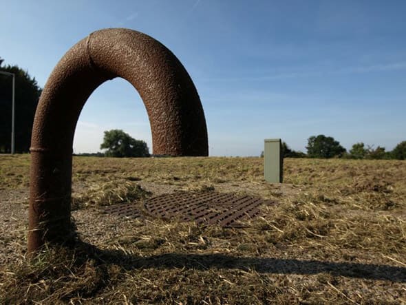
Then there is this one.
l2vAF_t18ewj.jpg


“What I told you was true ... from a certain point of view.” - Obi-Wan Kenobi, "Return of the Jedi"
 
MM - I agree the final look might be Ok, but that's why you need good site supervision / monitoring to pick up the misalignment before they cajole it into position....

ax1e - that's a cool photo.

I like these type of illusions

image_nt8fw8.png


Remember - More details = better answers
Also: If you get a response it's polite to respond to it.
 
LI,
I think " cajole" may be a term used in your part of the world but I understand what you were saying.
On a Shale Oil R & D project as a welder in the early '90s I witnessed a supervisor heating an elbow till it was glowing red whilst another employee poured water on it from a fire hose to try and correct the alignment of two weldneck flanges - one connected to the elbow.
When it was discovered I was a certified Welding Inspector I was promoted off the tools.
First thing I did was spray red paint on the elbow and have it cut out and replaced.
Not 100% sure of details as it was long time ago but pretty sure it was a Naptha line at around 300 degrees C.
This shit goes on everyday (I know, I was on the tools for 15 years) - as LI stated if you don't have competent supervision you have no idea what you are actually getting.
 
DekDee: I supervised piping installation as part of my responsibilities for many years. Though I've done lots of fabricating from about the age of ten, I've never been "on the tools" professionally. I've certainly been around enough to know what people are tempted to do, and are forced to do to get a job done, and why. And I know that a lot of it happens not because people don't know better in the field, but rather because people in a design office somewhere are deluded about what it takes to make piping actually fit with precision, and never get the chance to spend time in a fab shop or on a construction site to experience what happens when their assumptions come to naught. They've never pondered what tools for angular tolerance control a typical pipe spool fabricator has at his bench, nor done the calc of what it means to be 1/2 degree out on a flange to elbow connection in two planes, ten feet out...And then we have people wanting to take away the LEGITIMATE tolerance corrections they are afforded in piping design, because they don't "look right"...and sometimes they too are right, because the thing was either designed or fabricated so sloppily that it takes too much of a "cheat" in one of those legit measures to fix it- and the real fix- the one which would make it actually fit- is putting the job behind schedule and over budget...

I've seen "diamond heat" being used to pull things straight on numerous occasions, though without the firehose- that's a new one!
 
Ya we all know that right things look wrong and wrong things sometimes look right, but the second happens a whole heck of a lot less number of times than the first. Given that both are possible, go with the probability. I've got enough experience that I'm certainly not going to bet on something that looks wrong "is really right". Neither do I usually have the time to test it to see if it is right, plus the only way to test a lot of that stuff involves cutting it out, testing, measuring, etc. at which time you usually do find out it is bad anyway, so you just wasted more for testing time. I can also say, that if I saw something like that and passed it, just to have it fail on startup or something, I can tell you that my boss would be extremely happy... to kick my A into next Sunday and do it again Monday after, but he'd also have to wait in line to do it. I'd much rather take that chance on something that looked right. As for delaying the job, ya if you don't make it right the first time, it usually only gets worse later on. Making it right immediately on the spot pays dividends.

“What I told you was true ... from a certain point of view.” - Obi-Wan Kenobi, "Return of the Jedi"
 
Status
Not open for further replies.

Part and Inventory Search

Sponsor