Recently, many motors with 9 terminals have been appearing in workshops.
These motors are designed for one voltage and one speed.
For more information, please visit the following link: [URL unfurl="true"]https://winding.wixsite.com/design/post/unusual-example-from-practice[/url].
This new motor design appears to use a different starting method (hopefully will be useful for winders).
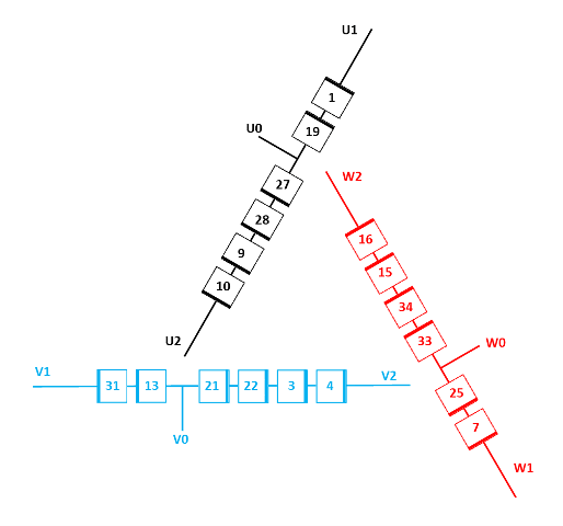
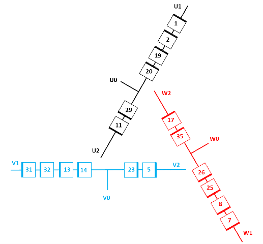
During the start, the motor is connected in a serial YD configuration, as shown in the attached diagram.
During the running period, the motor is connected in a simple 1Delta configuration.
Can someone explain this theoretical case, and how much the starting current decreases compared to other starting methods such as DOL, Y-D,or PWS?
These motors are designed for one voltage and one speed.
For more information, please visit the following link: [URL unfurl="true"]https://winding.wixsite.com/design/post/unusual-example-from-practice[/url].
This new motor design appears to use a different starting method (hopefully will be useful for winders).
During the start, the motor is connected in a serial YD configuration, as shown in the attached diagram.
During the running period, the motor is connected in a simple 1Delta configuration.
Can someone explain this theoretical case, and how much the starting current decreases compared to other starting methods such as DOL, Y-D,or PWS?