Tek-Tips is the largest IT community on the Internet today!

Members share and learn making Tek-Tips Forums the best source of peer-reviewed technical information on the Internet!

  • Congratulations TugboatEng on being selected by the Eng-Tips community for having the most helpful posts in the forums last week. Way to Go!

"Pinched" edges on surfaces

Status
Not open for further replies.

jones274

Mechanical
Joined
Dec 10, 2015
Messages
12
Location
IT
Hi,
I'm quite new on this matter so, please, forgive me for the possible trivial question:
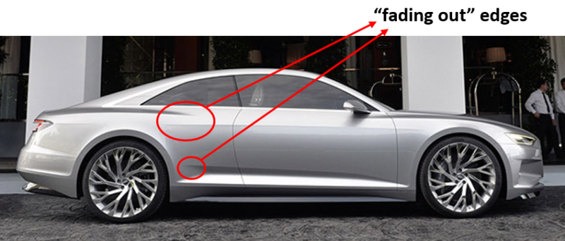
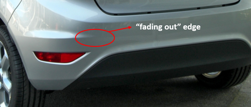
How are the surfaces containing a "fading out" edge generally designed into the various CAD environments?
Thanks in advance

fad1_ufpwiv.png


fad2_vfjf6b.png
 
It's probably easier to do in the actual sheet metal, by relieving the area between the highest curvature portions of the punch and the lower curvature areas, so the metal is sort of 'air bent' as it's stretched in that area.

In a CAD system, I'm guessing a command like 'loft', probably followed by a lot of manual buggering with the contours of the math model.


Mike Halloran
Pembroke Pines, FL, USA
 
Thank you for your answer.
Did someone have to face this problem in a common CAD environments? And how she/he managed to solve it?
 
The mold or stamping die was likely machined for all those parts. There are many CNC Cad programs that can do that sort of thing.
Catia is probably the best for it. You need to ask someone that uses these types of software.
 
Yes but I'm interested in how to model the "pinced" edges in 3D CAD. I'd like to understand if it can be done by using some sort of loft or by imposing the surface normals near the edge.
 
If you have access to a specific CAD package, try asking that package's experts, in the specific forum devoted to that CAD package.


Mike Halloran
Pembroke Pines, FL, USA
 
Ok, I'll try that. Thanks!
 
Status
Not open for further replies.

Part and Inventory Search

Sponsor

Back
Top