Continue to Site

Eng-Tips is the largest engineering community on the Internet

Intelligent Work Forums for Engineering Professionals

  • Congratulations SSS148 on being selected by the Eng-Tips community for having the most helpful posts in the forums last week. Way to Go!

"slider-crank"-style lift mechanism. What workaround to avoid dead point/singularity? 3

Status
Not open for further replies.

thorq

Mechanical
Sep 27, 2015
9
Hi, I am trying to design a lifting mechanism for a quite large (in area not weight) platform that only uses rotation for its actuation. I have a design that uses a mechanism similar to the slider-crank and I want to maximize the total height the platform can travel.

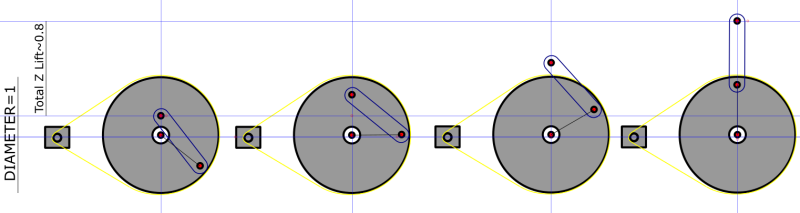
This is a sketch of my design:

screenshot.396_ybvv3i.png


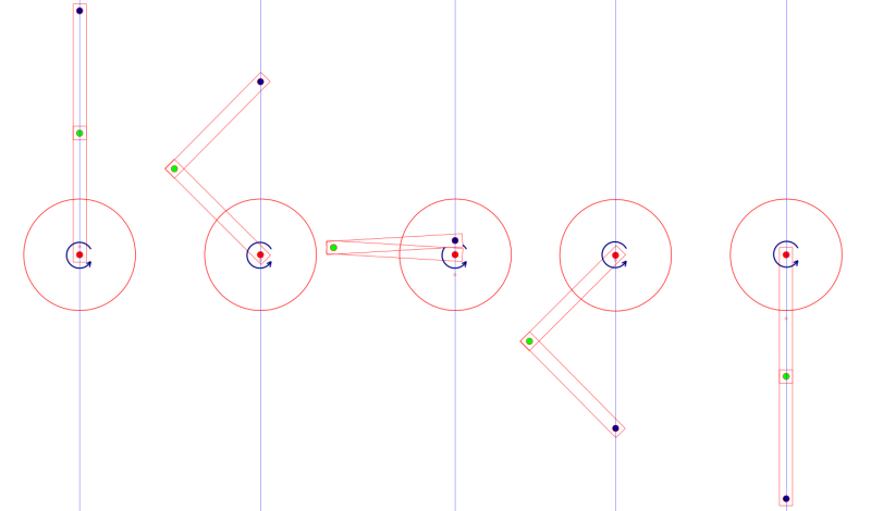
The rotation is going to be executed by a motor at the red dot and my dilemma is about the behavior of the two arms when they reach the position at the middle of above image. I think this is called a singularity or dead point.

If the platform is going down, the way I have suggested in the sketch, at that point I see a weak mechanical position when the platform will tend to fall more than it should because of its weight. This is where I would loose precision in movement and I need a solution to overcome this. Is this true? What are the weak points of this design? Just a note: there is going to be direction changes in rotation at arbitrary positions.

A preloaded spring was suggested to me but I don't exactly know how should that be setup, to which direction is better? Is there any other (simple/cheap) solution employed by other such mechanisms/robot arms?

I am also thinking about having gears at the green dot ends of both arms but that would introduce backlash when the rotation would be reversed.

PS: I don't want to change the slider-crank-based design to a leadscrew or something else, dut to other factors it has to be rotational.

Thank you for your suggestions.
 
Replies continue below

Recommended for you

If the drive has to be rotational, I would strongly consider using a roller chain and sprockets as the drive. I've seen it work successfully. Attach a driver pin to a single chain link. Insert that diver pin into a slot on your guided moving carriage.
 
Use a 4:1 length ratio between the crank arm and the connecting rod, and if that won't fit work your way down to a ratio that will fit. The crank arm to connecting rod length ratio as-shown in the graphic is too close to unity.
 
Yeah - at the crossing point there is zero load capacity, hence the dead spot.

If you add a fixed sprocket at the drive end and a sprocket at the pivot of the driven lever with a chain around them then the second sprocket will be driven to orbit the first and have moment continuity to continuously carry the load. A similar mechanism is used in orreries to drive moons around the planets.
 
I have built this mechanism on several occasions, and it works beautifully, at large or small scale, with fine pitch timing belts and with #40 roller chain:


... sorry about the long link.

The mechanism comprises a fixed sprocket of size 2N, about the center of which a primary arm is driven by obvious means, and a secondary arm free to rotate at the tip of the primary arm, and driven in rotation by a sprocket of size N. The two arms are of the same length L center to center, and the total stroke of the mechanism is 4L. The tip of the secondary arm is constrained to move in a straight line. There is no dead spot.

I think it's a derivative of work by James Watt, who built it with gears, not chain and sprockets, to get around a slider-crank patent. I think you can see how it would work with gears of size 2N and N and an intermediate idler gear of not quite arbitrary size.


Mike Halloran
Pembroke Pines, FL, USA
 
thorq- What would be of greater concern are the radial forces at the rotational joints as the mechanism passes through the 90deg position. In theory the radial forces at the rotational joints approach infinity as the linkage passes through center. In reality to prevent this situation you would need to have substantial clearance in the joints and/or very flexible mechanism structures.
 
Thank you all for the responses, please bear with me I am digesting the knowledge (I am in IT not ME).

1st: @Jboggs: I think your suggestion goes in line with 3DDave's and MikeHalloran's. I wonder how come I didn't find that video during my research, that would have saved you this thread. Nevertheless I am glad because I am sure I'll have many more things to ask.

I have seen the "How it's made" (Robot Arm on How it's Made ) for robotic arms but it didn't click to me that one of the many belts going from shoulder to elbow does exactly this.

@tbuelna: I can't have clearance in the joints or flexible arms/etc because this platform needs to go up and down with a certain precision, with no deviations from the vertical.

One more thought: if the initial position of the platform was up and it only descended, wouldn't the weight of the platform "help" it decide to go down at the singularity? This is what I was imagining when I started thinking about the application. The only mechanical problem would then be when I raise the platform all the way up, at that middle point it wouldn't choose to go above the center by itself, more likely it will go back down because of this weight bias.
 
thorq,
The other thing I don't like about the linkage approach is the wide variations in speed and torque as the constant rotary speed is converted to linear motion. You haven't mentioned a specific load or speed but normally that would be an issue.
 
My application will use stepper motors to rotate the pulley. In software it is possible to calculate how many motor steps this variable output will need for the next move. I don't mind the differences in speed between moves, my platform will move pretty slowly. The variations in torque are because of the position the load finds itself across the circumference of the pulley -e.g. at ecuator, when the load is max?

What about the weight of the platform helping overcoming the singularity indecision of the linkage? I am pretty interested in your opinions about this.
 
The weight will cause the linkage to suddenly go over center due to deflection of even tight joints. It's a place of zero leverage so the forces are otherwise infinite. Coming the other way the linkage will stall until enough deflection builds up and it surges to the opposite side.
 
Don't make the home position(s) top-dead-center and bottom-dead-center.
 
"Don't make the home position(s) top-dead-center and bottom-dead-center." and also "It's a place of zero leverage so the forces are otherwise infinite" so I guess my only option is starting a couple of degrees away from top and finishing above center.

I have sketched another design after I have realized funny things will happen at the center but I hoped there would be a solution to overcome that issue gracefully. Here's my sketch:

screenshot.398_b7tnyk.png


This will give me about 80% of the diameter the driving pin describes.
 
rack and pinion are very precise parts and therefore are expensive. And difficult to source in many areas. And they justify their price for some aplications but not for mine. In my design I only need to have precise holes and good enough bearings to build 3 such pulleys with arms. There will be no slider per se. having 3 or 4 of these will help each other keep themselves on the straight line.

I am thinking also about having 2 such pairs, with one pair having a slightly longer arm that would put it in a position other than the singularity and which will dictate the direction when the other pair is in the weak position. But I am still thinking about such a solution feasibility.
 
Roller chain is not terribly expensive, and when stretched along a frame, makes a serviceable rack.
You can buy specialized roller chain with some links modified to accept plates to make a conveyor and instead bolt the plates to a beam, but for vertical travel it may be unnecessary.

In your case, imagine pillow blocks and a lineshaft with sprockets along its length, all placed near the top of your apparatus, and lengths of roller chain supporting your platform. Tie the unterminated ends of the roller chain to a dangling length of pipe or bar just to keep some tension in the chain.


Mike Halloran
Pembroke Pines, FL, USA
 
It's about philosophy not money. Personally I can afford it but, being a reprap enthusiast, I can see the advantages of being able to produce the part you need when you need it, when something breaks, when you want another tool etc. I know that there are many folks around that surely can come up with an intelligent solution to my problem.

The difference is that instead of going the easy way, I set myself goals that would prevent me down the road to choose comfort. So I apologize for insisting but I feel I am quite close to a solution. If I need to lower my expectations I'd rather do that. @MikeHalloran's video suggestion proves it's possible, as well as his work if you believe him.

Back to my idea, having a platform to lift in a horizontal position you have to define the plane by at least 3 points in space. These points can be the upper ends of the rotating arm. Each arm can only rotate in a single plane, that's why the three will constrain a vertical movement.

Now we are left with the singularity issue. I know that pistons in a gasoline motor fire up in a sequential order to cover all 360 degrees of push -or at least that's how I came with the idea of having at least one of the slider-crank assemblies phase-shifted with 10-15degrees. This way it will still be in full torque when the other cranks will get in the weak position. What do you think would this work? Unfortunately I can't think of something even simpler that would stick to the goal of having rotary-only actuation.

Sorry for my long post, I expected at some point to be suggested some better alternatives that would go against my set goals.

PS: in my opinion, leadscrews/ballscrews/roller screws/rolling ring actuators are the best option for linear motion.
 
I was referring to the horizontal position. Top dead and bottom dead center are no problem. In the original diagram when the driven lever has the output lever fold back over it is when the leverage becomes zero.
 
If your device must provide controlled linear vertical movement/positioning of the platform using a reciprocating crank/conrod mechanism driven by a stepper motor coupled to the crank by a belt/pulley system, then I think you need to do a bit more detail design and analysis work. It would be very helpful to create a design spreadsheet that includes the mechanism kinematics, inertias/forces/moments in the system, and frictions at each joint contact. This will allow you to optimize the design of each component in your system and determine your motor power requirements.
 
Status
Not open for further replies.

Part and Inventory Search

Sponsor