Continue to Site

Eng-Tips is the largest engineering community on the Internet

Intelligent Work Forums for Engineering Professionals

  • Congratulations SSS148 on being selected by the Eng-Tips community for having the most helpful posts in the forums last week. Way to Go!

"slider-crank"-style lift mechanism. What workaround to avoid dead point/singularity? 3

Status
Not open for further replies.

thorq

Mechanical
Sep 27, 2015
9
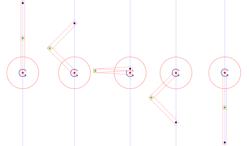
Hi, I am trying to design a lifting mechanism for a quite large (in area not weight) platform that only uses rotation for its actuation. I have a design that uses a mechanism similar to the slider-crank and I want to maximize the total height the platform can travel.

This is a sketch of my design:
screenshot.396_ybvv3i.png


The rotation is going to be executed by a motor at the red dot and my dilemma is about the behavior of the two arms when they reach the position at the middle of above image. I think this is called a singularity or dead point.

If the platform is going down, the way I have suggested in the sketch, at that point I see a weak mechanical position when the platform will tend to fall more than it should because of its weight. This is where I would loose precision in movement and I need a solution to overcome this. Is this true? What are the weak points of this design? Just a note: there is going to be direction changes in rotation at arbitrary positions.

A preloaded spring was suggested to me but I don't exactly know how should that be setup, to which direction is better? Is there any other (simple/cheap) solution employed by other such mechanisms/robot arms?

I am also thinking about having gears at the green dot ends of both arms but that would introduce backlash when the rotation would be reversed.

PS: I don't want to change the slider-crank-based design to a leadscrew or something else, dut to other factors it has to be rotational.

Thank you for your suggestions.
 
Replies continue below

Recommended for you

"PS: in my opinion, leadscrews/ballscrews/roller screws/rolling ring actuators are the best option for linear motion."

We've had lots of problems with resonances in long lead screw systems

TTFN
I can do absolutely anything. I'm an expert!
homework forum: //faq731-376 forum1529
 
You have guidance problems that are not yet considered. The crank-arm to connecting rod ratio gives high side forces that are going to create stick/slip issues unless you use nice linear bearings.

I've built slider crank mechanisms to move some biggish stuff and it is disappointing when you see what you haven't considered up close.
 
@3DDave: ok, that was my concern from the beginning, but I can only work around that issue with yet another system with 2 gears and a belt and I don't really like making this more complex. I can't really afford to lose accuracy at that crossing position, as you have mentioned that the linkage will suddenly go over center due to deflection, which means it will tend to travel more than the requested distance per stepper unit, with no way of knowing how much. If my 3 slider-cranks with phase-shifted crank angles will not avoid this issue by having the other cranks at non-dead-center angles to help, while keeping platform leveled, then I think I will ditch the first design altogether and focus on the second one, which resembles more the classic slider crank.

@dvd: I can't have neither the crank nor the rod too long due to size constrains (the lifting platform will end up having a too high lowest point) yet I want to maximize stroke.
I used the formulas at [URL unfurl="true"]http://ocw.metu.edu.tr/pluginfile.php/3961/mod_resource/content/6/ch7/7-2.htm[/url] and for an crank=100, rod=150, eccentricity=20 the stroke gets me around 203, which is acceptable.
It doesn't compare though to the stroke of the mechanism linked by MikeHalloran.

I will start putting together an excel with what info I have so far. I also need to calculate how much stroke travel for each stepper motor step, so that I can tune the dimensions/gear ratios for the desired resolution.
 
MikeHalloran said earlier that roller chain makes a serviceable rack and pinion. I would agree - to a point. Roller chain is designed to get its full strength when wrapped around a pulley to some degree. When the pulley is in contact with a section of straight chain, that contact is very limited, and likely to slip. That's why when I have used roller chain in linear motion I always let the chain move and attach it to a guided carriage riding on linear rails. The drive for the chain does not have to be at either end. It can be in the middle, but only if idlers are used to create some wrap on the driver pulley. To me, roller chain is a cheap, simple, strong, reliable solution to this design problem.
 
"Each arm can only rotate in a single plane, that's why the three will constrain a vertical movement."

From this statement it sounds like you aren't planning on using any guide features to constrain the platform to only allow vertical motion. You will likely end up with twisting/destruction of your mechanism without something holding it in the proper orrientation.

Yet another option you could consider looking into for vertical motion of a platform is a scissor lift.
 
Scissor lift still uses a linear rail.

It remains for a prototype to be built I guess... and improved from there. I am sure it's possible.
 
In the second paragraph of my last message, I gave a too-brief description of a cheap and simple mechanism used to lift large plating buckets out of tanks and such. In that case, the wrap on the sprockets is 180 degrees; the sprockets are rotated by a common lineshaft and a gear reduction. The roller chain is in direct tension from each sprocket to an attachment point on the heavy basket. The free end of the roller chain is attached to a simple bar that is heavy enough to provide tension on the chain so that it won't ride up on the sprocket teeth. In some cases, the bar is heavy enough to counterbalance much of the basket's weight. The lineshaft and sprockets are necessarily above the entire stroke of the basket, or in your case, platform. Lateral guidance on the plating line is provided by vertical angles/ rub rails, as some trajectory error from a perfect straight vertical line is acceptable.

The first paragraph discussed a different arrangement, where the roller chain is actually kept straight, and bolted or welded (!) to a straight bar to make a light-duty rack. As mentioned, it needs to be de-rated because of the zero wrap angle, or it needs to be fastened only at the ends and equipped with wrap idlers so it looks a little like a Rolamite. (Remember the Rolamite? Did anyone ever find a real use for it?)

I should also mention that working with stepping motors can provide a large number of surprises.
One of the first you will encounter is that every single step is a complete motion of everything, so the first problem in analysis is that you have to know the inertance of everything, and if it's too great, the stepper will buzz, but not move.
The second surprise is that the stepper's performance is integrally linked to the performance of the circuit that drives each coil in turn, so any comparisons you do have to include a particular motor and a particular drive circuit.
There exist many books on application of steppers (search on Al Leenhouts in particular), and you will need to digest several such books before you are properly equipped to apply a stepping motor to a particular problem.


Mike Halloran
Pembroke Pines, FL, USA
 
Actually my first sketch for this platform has rolamite bearings but that was more of a design exercise because I've never seen a rolamite bearing used anywhere and they still need precision flat surfaces to roll, plus a fancy metallic tape and they are in fact exotic devices that would be difficult to make.

Regarding your explanation, it would be very helpful for me to have some pictures to look at. Maybe you have some. Or maybe something similar... I have a hard time following especially as english is not my native language.

Thank you.
 
Status
Not open for further replies.

Part and Inventory Search

Sponsor