Continue to Site

Eng-Tips is the largest engineering community on the Internet

Intelligent Work Forums for Engineering Professionals

  • Congratulations GregLocock on being selected by the Eng-Tips community for having the most helpful posts in the forums last week. Way to Go!

"Tuning" a flow divider/combiner

Status
Not open for further replies.

dory321

Mechanical
Jun 28, 2020
2
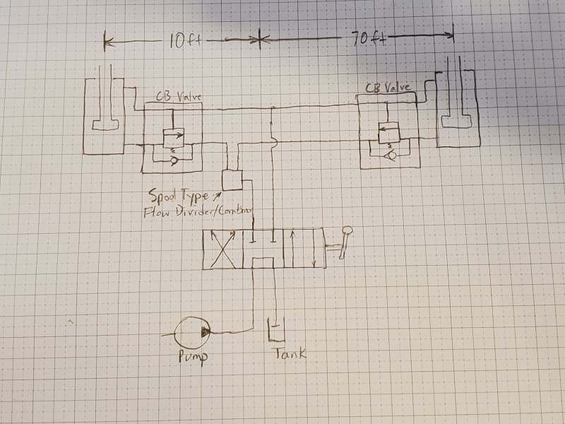
I built a one piece, hydraulic power lift door, 20ft tall and 60ft wide. It is raised using 2 identical hydraulic cylinders with a stroke length around 110in. I have the cylinders plumbed using a flow divider/combiner to split the flow to each cylinder equally, and counterbalance valves on the piston side of each cylinder so that it cannot be lowered without power.

My issue is that the error in the flow divider is not lifting the cylinders at the same rate. The flow divider is a cheaper, off brand, spool type model rated for +-10% error so it definitely could be my main issue. I also wonder if unequal hose lengths could be contributing. The power pack, directional valve and flow divider are located within 10ft of one cylinder, and 70ft from the other cylinder. The far cylinder is the one that lifts faster. I was wondering about adding a needle valve in the circuit of the close cylinder and attempting to tune the two cylinders with the needle valve to make the back pressure to each cylinder closer to equal. Would this work? Just wondering if I should give this a try before splurging on a new Sun flow divider....
 
Replies continue below

Recommended for you


Normally you already have a mechanical synchronization by the rigidity of the drawbridge.

The disadvantage of the flow dividers is that at the end of the race it can be desynchronized and that complicates the scheme to resynchronize.

I would make a circuit without flow divider with the 2 cylinders in parallel.
1) For the descent if I understand correctly you have a counterbalance valve on each cylinder. So just tighten the valve spring a little harder on the most loaded cylinder.
2) For the rise can you decrease the radius of action of the cylinder which arrives first if it is a door which turns? Or change the lifting point if it is a door that slides vertically? Otherwise add a pressure relief valve with non-return valve on the cylinder which arrives first. If it is a door that turns the balancing will not be perfect since the pressure due to the load varies depending on the stroke.
Good luck
 
On an elevator at the reception of supplies for an altitude restaurant where the load can vary from side to side: we put the jacks in parallel and synchronized with pulleys and a cable. It was less complicated and more rustic than solutions with proportional valves and position sensors or with synchronization valve.
 
It's never going to work right without mechanically linking the two sides or mechanically guiding the door with sufficient stiffness that it cannot skew in its guides. The latter is not going to happen for something like this, so you are stuck with the former.
 
Thanks everyone for the replies, I really appreciate it. I'll add some information and address a few things so we are all on the same page. First, I will attempt to upload a rough schematic of my circuit along with a picture of the door/cylinders.
20200628_200440_oghknq.jpg


Screenshot_20180329-205359_vv8ggd.png


There is no mechanical linkage between the two cylinders besides the 60ft wide door itself. It does not provide any stiffness between cylinders and happily flexes with no damage. I have thought of ways to mechanically link the cylinders with cable and pully but it isn't really necessary. I know it isn't necessary in this application because this is my second door of similar design. The first door has been been working well for the past 8 years with no issues. The original door has a SUN flow divider/combiner and all hose lengths to each cylinder were made identical to have equal pressure drops to both cylinders. The original door opens and closes and is never more than a few inches from being perfectly in sync.

The spool type flow divider/combiners have a bypass/syncing port built in so the cylinders can re-sync at either end of their strokes.

There are two main differences between the first door and the current one that I have issues with. First is the current flow divider/combiner is a no-name, off brand that i used to keep within budget. It was about one-fifth of the price of the SUN valve used in the first door. The second change is that I used appropriate hose lengths, therefore the hoses to the far cylinder are approximately 60ft longer than the close cylinder hoses.

I have a small needle valve that I am planning to install between the flow divider and the near cylinder. My thinking is that I can use the needle valve to create some resistance in the circuit which would keep the flow divider spool centered closer to it's neutral position. I have noticed that the uneven flow dividing only happens on the lift/extension portion of the cycle. I think this is due to having the ability to adjust the counterbalance valves on each cylinder independently to provide an equal rate of decent/retraction.

If the needle valve doesn't work I will likely order the SUN flow divider and try that. I look forward to any suggestions/ideas/replies you may have. I'll try to keep everyone updated with my progress.
 
I think you are right, a needle valve will do a little pressure drop. This will compensate for the difference in pressure drop of the pipe lengths or the poor 50/50 ratio of the divider. Reverse divider outputs?
 
Status
Not open for further replies.

Part and Inventory Search

Sponsor