Continue to Site

Eng-Tips is the largest engineering community on the Internet

Intelligent Work Forums for Engineering Professionals

  • Congratulations GregLocock on being selected by the Eng-Tips community for having the most helpful posts in the forums last week. Way to Go!

Rack and pinion lift 3

Status
Not open for further replies.

m.ahsaniftikhar

Mechanical
Sep 14, 2020
16
Hello all,

I am trying to design a telescopic elevating platform based on a rack and pinion configuration. The design is based on this video from youtube (click the link here). The video shows this in a horizontal configuration. I want to use this mechanism to build a vertical lift. For that, I need to perform some calculations. The telescoping effect achieved by this mechanism is of practical use in compact applications. Can anyone please help me out with the calculations needed to size the motors and the size if the rack and pinon for this? Please see the diagrams attached to get a better idea of the problem. I am particularly stuck with the effects of friction in this system.
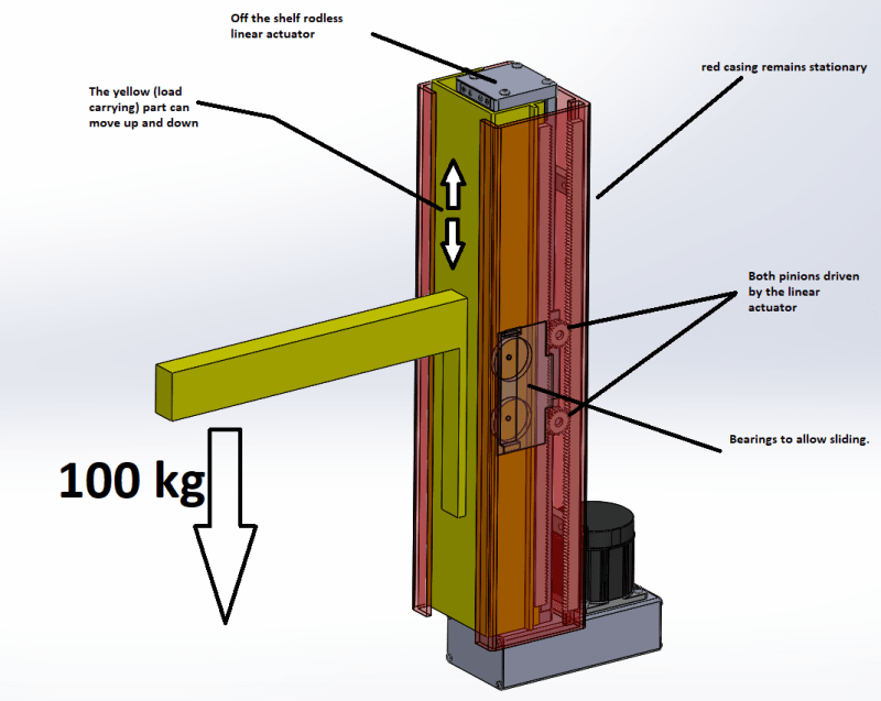
lift_mmhoor.png
 
Replies continue below

Recommended for you

Is there a particular set of features that would introduce high friction? It seems to be designed to ride on bearings - which would have very low friction.

I don't see anything about required speed. It looks to me as if you actually have rotary torque being transformed to linear motion by the pinons, and not a linear actuator?

To get a rough idea of torque requirements, multiply the mass being moved by the radius of the pinion gear. Could probably subtract 10% for efficiency and go from there. If it is a linear actuator after all, then you already have your force laid out here with the mass...

I just checked the video; it does indeed seem to be an electric motor and not an off the shelf linear actuator...
 
@onatirec, the linear actuator in the center moves the pinion gears. The utility of this mechanism is the magnification of the stroke. For every inch the linear actuator moves the pinion gears, the load borne by the yellow component moves 2 inches. I am concerned about how much energy will be lost due to friction produced between the rack and pinion. The speed of the lift is fairly slow, around 1 meter of travel in 7 seconds.
 
oh I see: you are effectively doubling the moment arm of the gear radius to get more distance at the expense of doubling the force.

From what I understand, rack/pinions have quite good efficiencies. I remember an automotive analysis that calculated steering rack and pinion at ~98+% efficiency. I suspect it is further to your benefit that you're moving a mass vertically - so that you don't really have gravity amplifying the friction force.
 
This is an old mechanism concept - usually it uses cables and pulleys to avoid the problems from gear tooth wear and subsequent failure.

Are you concerned with energy loss because there is a limited amount of energy available?
 
I believe that a single stage rack and pinion can be over 95% efficient. You have 4 meshes so .95^4 = .81 efficiency. Of course the gear load is divided with your dual pinions so take a look at the load per gear. You'd want cleanliness and the right grease to get the high efficiency. You might get by without out tight tolerances if you don't care about backlash (vertical is always preloading it?). You'll want to do some research to see if 20 Deg. PA or 14.5 Deg. PA is more efficient.

You probably already know that spacing the bearings farther apart will reduce the load (and friction) on each bearing.
 
You would need to be aware of separating forces tending to push the rack and gears apart.

Ted
 
There are two parallel gear mesh pairs and the efficiency is no different than one wider gear with two meshes, so .95^2, if the base efficiency is 95%. In practical effect it is unlikely that the gears will share the load, at least until there is significant wear.
 
The reason why I am not using pulleys and cables is that in vertical applications there is a higher chance of a catastrophic failure due to the cable or the chain snapping. My application puts a high priority on safety. Rack and pinion seems to be a safer bet from what I have read. Would you agree?
 
I am quite curious about the formula you used to calculate the effective efficiency. Can you please provide me a reference for this for further study and of course to reference it in my documentation.
 

A very interesting point about using a wider gear instead of two. Also, the point about load sharing was a very useful tip. Thank you for this. Do you have any other points for me to look out for?
 
Forklifts use chains for telescoping masts, along with a hydraulic cylinder. Do not reinvent the wheel.
 
If you want safety from power failure then why not a jack screw?

Remember - More details = better answers
Also: If you get a response it's polite to respond to it.
 
The force on a gear tooth has both a tangential and a radial component.

Ted
 
I was assuming that the meshing distance between is maintained by the bearings. So the rack isn't going to experience a radial force. Please correct me if I am misunderstanding this problem.
 
Seems to me that a wheelchair lift needs to be fail-safe, which is not something that a rack and pinion would provide, i.e., if the motor fails, will the chair precipitously drop to the ground?

A hydraulic lift would require a much more catastrophic failure to cause injury, since a pump fail would cause the fluid to flow back, at a relatively slow rate.

TTFN (ta ta for now)
I can do absolutely anything. I'm an expert! faq731-376 forum1529 Entire Forum list
 
Hello,

I'm in agreement with the others regarding fail-safe operation. Also, I don't think 100kg is nearly enough of a design load to ensure a factor of safety when dealing with human payload.


Kyle
 
Status
Not open for further replies.

Part and Inventory Search

Sponsor