Continue to Site

Eng-Tips is the largest engineering community on the Internet

Intelligent Work Forums for Engineering Professionals

  • Congratulations GregLocock on being selected by the Eng-Tips community for having the most helpful posts in the forums last week. Way to Go!

Rack and pinion lift 3

Status
Not open for further replies.

m.ahsaniftikhar

Mechanical
Sep 14, 2020
16
Hello all,

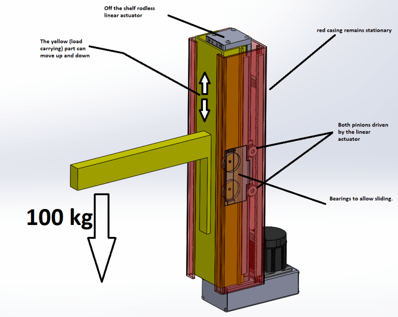
I am trying to design a telescopic elevating platform based on a rack and pinion configuration. The design is based on this video from youtube (click the link here). The video shows this in a horizontal configuration. I want to use this mechanism to build a vertical lift. For that, I need to perform some calculations. The telescoping effect achieved by this mechanism is of practical use in compact applications. Can anyone please help me out with the calculations needed to size the motors and the size if the rack and pinon for this? Please see the diagrams attached to get a better idea of the problem. I am particularly stuck with the effects of friction in this system.
lift_mmhoor.png
 
Replies continue below

Recommended for you

To me the more important concern, by far, is the safe guidance and support of the lifting structure. When the potential for human injury is involved, that is a MUCH more important question than quibbling over the finer points of drive efficiency. In fact, if I were doing this, the question of drive efficiency would be so far down on my list as to be almost a non-factor. Once you have a linear motion guidance structure that will adequately support and guide a 200 lb with load with significant off-center loads and a HUGE safety factor, then and only then would I look at actuator options. And the last thing I would do would be to design a new one from the ground up. Get a commercially available unit that has already been through all the testing necessary to sell it on the open market.

Make sure in your design that the actuator itself sees NO off-center or moment loads. They should all be absorbed by the linear motion guidance system. Also make sure that there is some freedom between the linear motion of the actuator and the motion of the linear motion system. Their lines of motions will never match perfectly.

This is one of those projects where the younger engineers can learn from the scars of the older ones. You design by the book. Then double it. Then, if human safety is involved, double it again.

One more tip - Keep this picture plastered firmly at the front of your mind during the entire project: You sitting in the witness stand defending your design to a plaintiff's attorney while the man that was injured on your lift is sitting in front of a very skeptical lawsuit jury. I guarantee that you will NOT be asked about the efficiency of your drive mechanism.
 
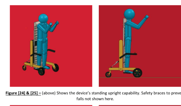
What do you make of the overall design though? This module is to be placed within a wheelchair itself. It will allow for the chair to go all the way up to the eye level of another person, and all the way down to allow for floor access. Therefore the design has to be compact and hence necessitates the magnification of linear actuation by adding the rack and pinion to multiply the effect of the linear motion. For reference, I am attaching the image of the concept I am trying to develop (which is by no means to the proper scale.) Would you use rank and pinion? or would you use a pulley and chain? or something else?
IMG-5254_hfso3c.png
IMG-5255_xy4uz9.png
 
Without a doubt I'd use a ball screw, chosen so that it would not back drive under loss of power at any reasonable service load for the application.

If I needed travel multiplication I'd use a telescoping ball screw, which has a maximum length >2 x the minimum length. But in my opinion for this application that's unnecessary.
 
Look in your very first picture at the "bearings to allow sliding". They are very close to each other. Why does that matter? Because the force that each bearing sees (and therefore the force that it imparts to the slide surface) is directly related to the distance from the other bearing, inversely. For example, if a 200 lb payload is 12 inches horizontally from the center of the upper bearing it creates a 2400 in-lb moment about that bearing. Lets assume the lower bearing is 6 inches below the upper bearing. That means it would see a 400 lb load to balance that moment. Both bearings would see 400 lb loads in opposite directions. That also means that your vertical rail surfaces would see 400 lb point loads. The shell appears to be extruded so I am assuming aluminum. I don't think that will work. I would strongly recommend you separate your bearings as much as possible, at least 12 inches apart.

That separation will affect your final configuration. Look at Fig 23. In that position the lower bearing on the lift carriage would be at least 6 inches off the floor, probably more like 8 inches. That means the upper bearing would be 20 inches off the floor in the full down position. Now look at fig. 25. It looks like the lift carriage has traveled upward maybe 30 inches? In that position the upper bearing would be 20 + 30 = 50 inches off the floor, which means the stationary rails will have to be at least that tall. This has nothing to do with amplifying the stroke of the actuator. This is simple linear guidance support, not even considering how it is powered. You could of course use a telescoping travel mechanism like one sees on some fork trucks or manlifts, with the accompanying complications and load calculations. But either way you should keep as much separation as possible between the bearings on the lift carriage.

If you do insist on keeping some travel amplification, be aware that you are magnifying the actual load on the actuator by the same ratio. Double travel = double force, regardless of whether the mechanism is rack and pinion or chain and pulley.

If it were me I would avoid rack and pinion for several reasons. Alignment of travel is ABSOLUTELY critical. You MUST maintain the exact same mesh at all times through travel. A tiny variation (from small frame deflections, etc) makes a huge difference in the load and friction that individual teeth see. The teeth will wear out very quickly and eventually fail. Think about this - there is a reason that commercial gearboxes operate with the gears in an oil bath. If I were forced to design some travel amplification (First I would resist it strongly) I would use a roller chain and sprocket, which the same method used on almost all telescoping forktrucks. Anchor a chain at one end. Send it up and over a sprocket driven upward by your actuator. And tie the other end to the lift carriage. Easy, peasy. Alignment is not an issue and neither is lubrication.

So, after you've done all this designing, building, trialing, redesigning, rebuilding, retrialing, redesigning again, building again, and retrialing again, you will arrive at this conclusion - I should have used a commercially available linear guide arrangement, a commercially available actuator, no amplification, and saved myself lots of time, money, and heartache.
 
SwinnyGG said:
Without a doubt I'd use a ball screw, chosen so that it would not back drive under loss of power at any reasonable service load for the application.

Absolutely false. Ball screws back drive easily because of their low friction. Lead screws would be better yet a brake is always recommended.
 
might be an application for Tsubaki's zip chain actuators -
I don't think that a single actuator has the capacity required, though.

Telescoping booms on cranes definitely work, so there is probably a way to get it done.

Looks like development with 3-D models will only get you part way there.
 
FACS said:
Absolutely false. Ball screws back drive easily because of their low friction. Lead screws would be better yet a brake is always recommended.

Uh.... no. Ball screws can be spec'd both off the shelf and customized in configurations that will not back drive. I've done it literally hundreds of times in my career.
 
The screw drive just seems so much simpler.

The rack and pinion only gets to use ~ 1/2 the available height.

Screw can use ~80% or more.

Inside of the linear actuator is likely ..... a screw anyways.
 
Status
Not open for further replies.

Part and Inventory Search

Sponsor