Eng-Tips is the largest engineering community on the Internet

Intelligent Work Forums for Engineering Professionals

  • Congratulations waross on being selected by the Tek-Tips community for having the most helpful posts in the forums last week. Way to Go!

Radius to a reference 2

Status
Not open for further replies.

JModelsalot

Mechanical
Nov 29, 2021
16
0
0
US
Super Users, I need some help.

!This might be simple but I cannot seem to find the right settings to make this work.!

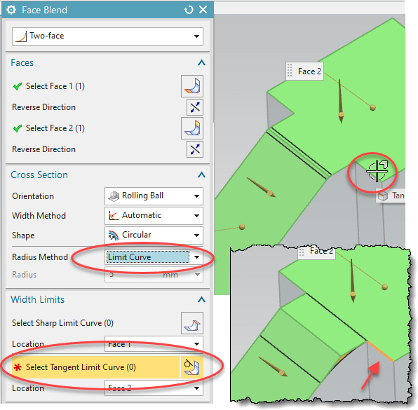
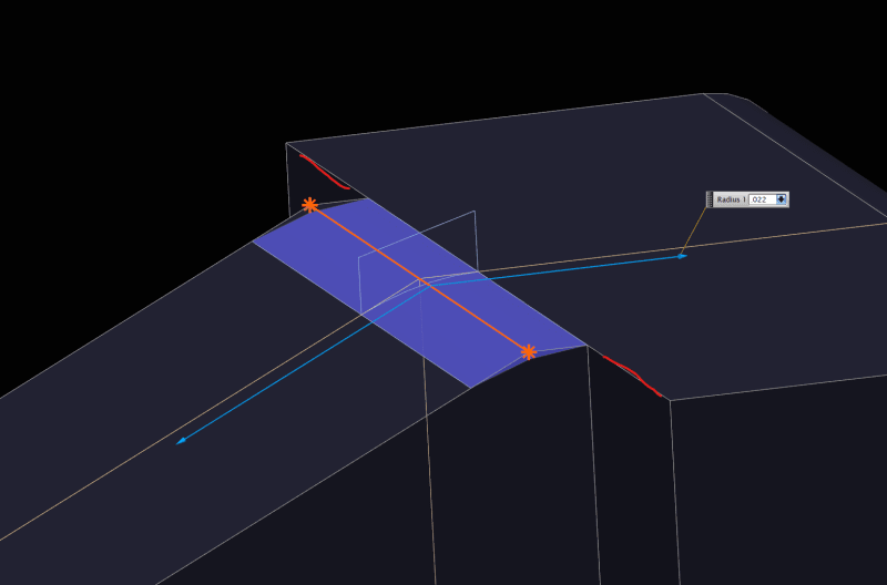
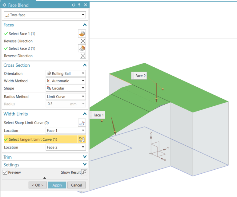
I want to make a radius and rather than place a size I want to select a reference surface to drive the blend size.

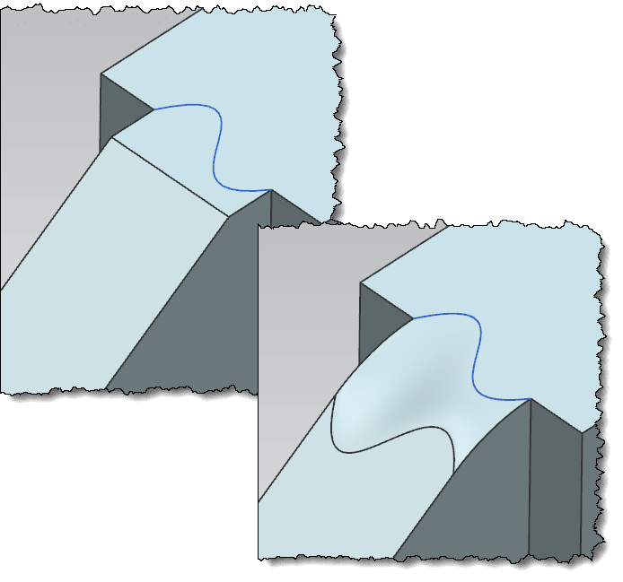
I have sketched a G2 tangent blend so I know what the radius needs to be, but I would like to not need to sketch geometry to find the dimension if possible.
I tried using a measurement and creating an expression to drive this feature, but again it would be great if I could select the edge.

I need pro pointer #277 to make this work appropriately....

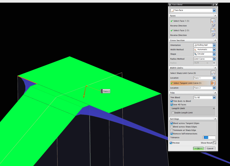
Image attached. Red lines are the desired reference surface.

Radius_Screenshot_krbftj.png
 
Replies continue below

Recommended for you

Thanks Cowski but I'm not able to reproduce. I think the issue for me is the additional step on what you have as Face2. Its tough to see in the image I uploaded so my apologies there. Hard to help with an answer when you dont have the whole story.

Try adding this and see what you think. I think the angular face in the opposing direction is the issue.

Radius_2_azwq5c.png
 
G2 is curvature continuous, in the pictures the curvature is zero on both surrounding faces.
that means that the blend should gradually loose the "blend" and become/be flat at the tangent lines.
By that there is no longer a fix size, since the curvature acceleration and deceleration can be any "speed" to that edge.
If we place a circle, there is a fix size when tangent occurs on both sides.
this is what Cowski's example shows and does. In case your geometry is more complex than the example, you can create the dividing curve and use that for the blend.
2021-12-08_18-47-24_astma0.png

Below is an example of two surfaces , both are G2 at the edges to the surrounding faces.

Regards,
Tomas


Never try to teach a pig to sing. I wastes your time and it annoys the pig.:)
 
Thanks for the input its appreciated.

There should be a parasolid attached to this reply.

Toost, I can create a simple sketch/extrude to create a radius tangent with both edges that has its size driven by the limit face and all is well. What I dont want is to create an additional sketch entity or use a measure expression to drive this feature. I'm guessing the additional steps are not needed but I'm missing a setting in the feature creator.

 
 https://files.engineering.com/getfile.aspx?folder=4c20325a-a5d3-429d-92e6-2f34a934c98b&file=Radius_Model.x_t
Cowski,

I'm running 12.0.2.9 and it says I'm unable to open due to it being created in a newer version. Would you mind posting a screenshot of the feature settings you used?
 
Cowski,

I appreciate the efforts with taking a look at this stuff but I cannot get that feature re-created in my model. I attached a screenshot as to what I get, which is the reason that I had asked for help. I dont understand why the radius wants to extend out into space. I tried selecting the sides in the direction of the radius extents as well but I am having no luck. No need to spin your wheels on this further, I can create an extrude and save us both some time.

Thanks again for the responses.
Radius3_inkhlz.png
 
What i am trying to say is that
1) There is an exact matching size if the blend is circular ( G1) but not if you go G2 -then the cross section is no longer circular and the size can be "any". The image I attached in my prevous post should show this, 2 surfaces which both are G2 at both ends.
2) Cowski shows one way of creating this without the sketch. He applies a Face blend where the size is dictated by that "Tangent limit curve".
In the example below i could use the edge to the side of the actual touch. but you can also draw a curve on that surface and use that. I drew a s-spline to show that.

2021-12-09_11-07-40_jyogcg.png
2021-12-09_11-14-52_u9hdkp.png


Regards,
Tomas

Never try to teach a pig to sing. I wastes your time and it annoys the pig.:)
 
I'd also suggest using examine geometry on your model.
faq561-2116
In addition to the checks mentioned in the FAQ, I'd suggest turning on "misaligned" and "spikes/cuts". Some errant geometry in your actual model may be causing issues for the face blend.

www.nxjournaling.com
 
I have yet to use the examine geometry command but I will give that a look and see if there is some errant geometry causing the failure.

Toost, I understand what you are saying in regards to the G1,G2 curvature but I'm not concerned with how smooth that tranistion is, rather I want to get a transition within a single feature instead of creating sketch geometry or using another command. The solution Cowski has offered is great and now I need to explore why I am unable to reproduce.

Thank you both for taking the time to consider the question.
 
Try reset the face blend dialog. It has historically been having the habit to "remembering bad settings that makes the next blend fail."
Reset cures that habit.

2021-12-10_09-48-10_pkkebx.png


Regards
Tomas

Never try to teach a pig to sing. I wastes your time and it annoys the pig.:)
 
Status
Not open for further replies.
Back
Top