Eng-Tips is the largest engineering community on the Internet

Intelligent Work Forums for Engineering Professionals

  • Congratulations waross on being selected by the Tek-Tips community for having the most helpful posts in the forums last week. Way to Go!

RAFTER TIE angled cables 4

Status
Not open for further replies.

Materofact

Civil/Environmental
Feb 21, 2015
42
0
0
US
not sure why my brain is being thrown for a loop about this. this is why i like trusses by others...

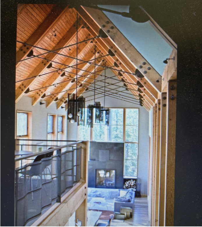
Please see attached picture. basically, an architect wants this look (ya...architects)...... 2 cables for each rafter criss crossing. However, 165 lb factored snow load and 30# dead load per foot on a 24' wide room. Architect wants 8 foot between the rafters! (perpendicular framing between). 8/12 pitch, upper attachmnet of cable is about 4 foot horizontal distance from the ridge.lower attachment is about 1 foot above the plate hieght.

simple calcs (and strucalc type) analysis shows 16k for a typical rafter tie tension at both ends for a connection about 1 foot above the plate, *a little more when you resolve the angled connections.....but with TWO cables the connection should be half of a single member? 10x18 rafters is what i come up with, and about 9kk bolt reqauired connections into the wood. rafters need be designed for the cable loads in addition to the snow and dead, ofcourse. seems huge..?? AND...What about wind thrust INWARD? does roof diaphgragm take care of that once you get it up into the rafter?? how bout stiffening up the ridge joint with a bolted steel gusset?
 
 https://files.engineering.com/getfile.aspx?folder=acf33acf-f77e-4b75-8d8e-345c458d97ab&file=61464316204__70A3E587-F4CF-4629-99AF-ACDB10B8E501.JPG
Replies continue below

Recommended for you

Materofact,

Looks like the slope in the photo is more like 12/12 than 8/12; and it looks like the connection point was further down the rafter, maybe about midpoint, giving the rods a greater lever arm about the ridge node. The ties are definitely eccentric to the rafters. You could alter the geometry to match the photo, but the rafters would then rise 12' from the top of wall to the ridge.

Calculating the bending moment and axial force in the rafter under gravity loading is pretty straightforward, but it's easy to make a mistake if you're doing it by hand. Removing the eccentricity of tie load seems to be a sensible plan.

image_zvnwyo.png


BA
 
Materofact,

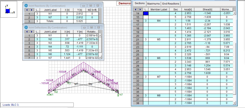
This is an analysis results that might be useful in sizing the members. Note the load case is 165 plf snow plus 30 plf dead load. The ridge point is pinned, with 2x12 rafters, and 1" dia. rods. M1-M6 are rafter segments from bottom up.

image_j9b3hn.png
 
Materofact,

I did an analysis on the truss with 4x16 rafters (2x2x16) and 1" rods, it seems worked, you might want to give it a shot.
 
retired13,

[li]The factored load specified was 165psf snow + 30psf dead load. The rafters are spaced at 8' o/c, so the total factored load is 1560plf.[/li]
[li]Your output shows a total load of 5625# which would be equivalent to 234plf on a 24' span which doesn't agree with either 195 or 1560plf.[/li]
[li]If your sketch is to scale, it appears N3 and N5 are each about 6' horizontally away from the ridge, whereas the OP indicated they should be 4' horizontally each side of the ridge (see below).[/li]
Materofact said:
Please see attached picture. basically, an architect wants this look (ya...architects)...... 2 cables for each rafter criss crossing. However, 165 lb factored snow load and 30# dead load per foot on a 24' wide room. Architect wants 8 foot between the rafters! (perpendicular framing between). 8/12 pitch, upper attachmnet of cable is about 4 foot horizontal distance from the ridge.lower attachment is about 1 foot above the plate hieght.

I'm not sure what you expect the OP to do with this information since your input does not correspond to the given data.

BA
 
retired13,

I agree that 165psf factored snow load sounds a little outlandish, but the point is, this was the information given. Perhaps Materofact could comment on how such a high snow load was obtained.

image_cw7vnr.png


But aside from that, your reactions do not agree with your stated loading and your geometry appears to be incorrect, although you did not list the coordinates of the nodes, so I can't say that for sure.

BA
 
Geometry: 24' span, 8' roof height, rod 4' below ridge, 1' above eaves. Load: 165 plf snow, 30 plf dead load (as described by OP as quote above). The high snow load was my concern, so I asked again to confirm the span of rafters, as I was assume 20 psf roof snow in my original thought. The reaction is a little off, I did the trick learnt the last time at no avail, so I'll need to track the source causing the difference again. But, albeit the difference (+20%), the outcome is favorable, and the OP can easily adjust for it.

Using 2-2x16, the deflection seems acceptable. My concern is whether the rafter is adequate for 9k-ft moment, and 3.5k axial force.

Note: Source of the difference : the load was applied to hypotenuse rather than horizontal projected length.
 
retired13,

If your interpretation is correct, this entire thread has been a waste of time for everyone concerned. The OP should clarify the snow load and the geometry of the structure.

BA
 
BA,

Language-wise, how you interpret this,
"However, 165 lb factored snow load and 30# dead load per foot on a 24' wide room."

If your assumption is correct, then just place the rafters at 12" o.c., or tell the architect to change the roof slope to minimize the snow load. Nothing is wasted, every comments provide insights to whether it works or not.

 
The language is not clear, retired13. I've heard people say "pounds per foot" when they meant "pounds per square foot". But he went on to say:
Materofact said:
simple calcs (and strucalc type) analysis shows 16k for a typical rafter tie tension
which led me to believe he meant the latter but I admit, I could be mistaken.

If you don't mind, can we drop it? The OP is not clarifying and I am tired of discussing it.

BA
 
You could be right, with factor of 8, the tension in the cable close to 16k, but not quite there, Yes, this is the end of story, unless the author say something.
 
sorry for the delay.. appreciate the attention and comments...

snow load is huge, in ca sierras... so yes, factored load is in fact 165#/sf. and dead load of 30#/sf just to account for the gigantic required members. 195#/SF
 
It is common for roofs in ski country to be built at 24/12 to reduce the load. The roof in the image is steeper than 12:12 and was not built with economy in mind. Prettiness was the driving factor as nothing in that is cost effective unless you want that look.
 
Retired, codes I work with report ground snow load and you apply factors to that to determine roof snow load. Most codes have factors that relate to roof slope and sliding snow. Tin finishes coupled with a steep slope helps. To have a notable load reduction you need steeper than 12:12 in codes I am familiar with.
 
OK, I didn't read this whole thread (sorry) but am I the only one that notices that the two wood members appear to be separated by a steel plate? There is a definite gap there, and I can't see them leaving the gap unfilled as it would be a b***h to finish. I'm guessing this is designed as a flitch plate with a nice thick steel plate taking most of the load.
 
Good spot on that gap, SteelPE. I suspect you're onto something.

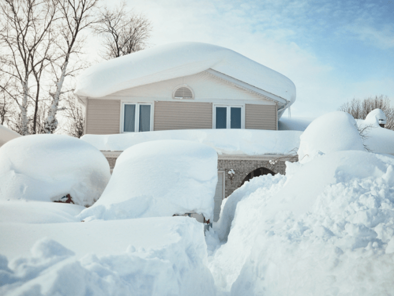
Just a tid-bit of information regarding large snow loads from someone who deals with them a lot (recent project had a ground snow load of 11.8 kPa):
- Creating a steeper roof with a slippery surface can drastically lower your applied snow load, but it does not come for free.
- In order to actually get snow to shed off the roof instead of accumulate, the roof surface needs to be extremely well ventilated to prevent ice damming.
- "Slippery" roofs don't necessarily stay that way. A dark-coloured roof may warm in the sun, and a correspondingly immediate snowfall can stick, therefore rendering the roof surface quite rough and causing snow to build up for a significant time period.
- Any snow that does accumulate on the roof will put large sliding forces on the roof finished surface and connected members, which can cause all sorts of headaches. Big snowpacks can rip standing seam metal roofing right off, but more commonly, causes a bearing failure at the fastening screws, elongating the holes, and resulting in widespread leakage. I've seen chimneys that were pulled right off a roof.
- Roof avalanches can cause significant damage to people and property that is in the wrong place, which can result in restrictive closures to areas threatened by the roof. The fallen snow can also end up resting against the building walls/windows, causing a whole suite of problems.
- If you are in a seismic zone, don't neglect to include a portion of the accumulated snow load in your active mass. It can make a difference in high snowpack areas.

Due to the above, some of the projects that I have recently been involved with have gone to extremely low-slope roofs to reduce the avalanche, roofing material damage, and other concerns. We end up with pretty huge gravity loads, but it gets rid of so many other problems.
 
SteelPE,

This is a double rafter setup with cables as tension tie. The gap is room for the cable connection.

CraigH,

All roofs have their own kind of problems. Mine and several neighbors' flat roof had clasped after an unusual snow event, but the pitched roofs were fine. However, I still specify and design flat roof though, it depends. For this job, steeper is better for the fancy concept that uses cable as tension tie.
 
Status
Not open for further replies.
Back
Top