Continue to Site

Eng-Tips is the largest engineering community on the Internet

Intelligent Work Forums for Engineering Professionals

  • Congratulations waross on being selected by the Eng-Tips community for having the most helpful posts in the forums last week. Way to Go!

Railway Pipeline Stress Analysis - design factor 4

Status
Not open for further replies.

Miaaa1101

Civil/Environmental
Jan 19, 2022
3
Hi everyone, I'm working on aa pipeline stress analysis crossing the railway and I'm referring to API RP 1102 (2017) and ASME B31.4 -2006.

Starting from API RP 1102
My pipe can pass the "allowable stress check“ with 0.72SMYS. Let's call F1=0.72
However, it failed for the "total effective stress check" with 0.72SMYS. Calling F2=0.72

I'm trying to find out that for the total effective stress check, I can use 0.9 SMYS instead of 0.72. (Does F2 need to equal to F1?)
The words in API RP 1102 are vague, it only mention that F2 should be consistent with standard practice or code requirement.

Then I went to B31.4, in table 403.3-1, it does mention that the "effective stress at railroad" can use the F2=0.9. However I cannot confirm if the two codes are talking about same case.

Does anyone perform the analysis before and could share some light? I don't feel very comfortable to bring the design factor from 0.72 to 0.9 for the gas pipe without a solid reference....

Thanks ahead!
 
Replies continue below

Recommended for you

I believe you can use F=0.9 for the total effective stress check.

Table 403 gives you that value (0.9) for cased or uncased pipe.

I think the wording is quite clear - for effective stress you use the value in your design code - in this case 0.9.

Remember - More details = better answers
Also: If you get a response it's polite to respond to it.
 
You are crossing under a railroad without using casing?
That is seldom allowed by railroad companies. Interesting

B31.4 obviously does not apply to gas pipelines, although 1102 can be used for both.
Regardless of what 1102 allows, B31.8 conditions must also be completely satisfied.
 
In the past RR competed with pipelines to carry oil. Because the RR were generally in place first, they did all they could to stop or increase cots of pipeline construction. So , I agree , even if not clear in the rules , I would use casing under RR, or someday you are likely to be sued.
 
Thanks ahead for everyone's reply!

More details here: actually we're going to construct the railroad over the existing uncased gas pipeline, we will have ~10ft embankment over the existing ground and also over the existing pipe. We're trying to perform the stress analysis for the new embankment to see if the pipeline is considered still safe under the new rail live load and with the deeper burial depth...otherwise we will likely propose protection concrete slab or so to protect the pipelines on site.

And then it comes to my original question, my pipeline can pass the "Barlow stress check" with the design factor of 0.72, however it failed the total effective check if we apply same 0.72 design factor. (0.9 will pass though). I felt confused because in the calculation example of 1102, the code applied 0.72 for both Barlow check and total effective check.


Dear Miaaa1101 (Civil/Environmental),

Please find below my points for the thread;

- ASME CODE FOR PRESSURE PIPING, B31.4 is for PIPELINE TRANSPORTATION SYSTEMS FOR LIQUID HYDROCARBONS AND FOR OTHER LIQUIDS
- THE RELEVANT CODE FOR GAS DISTRIBUTION AND TRANSMISSION IS ASME B31.8 WHICH IS MORE STRINGENT,
- YOU CAN FOLLOW API RECOMMENDED PRACTICE 1102 AS LONG AS YOU COMPLY WİTH THE REQUIREMENTS OF B31.8
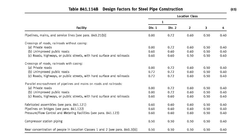
- DF VARIES WITH LOCATION CLASS ( CROSSING AT CROWDED CITY CENTER , SUBURBAN, RURAL ...) PLS LOOK 840.22
- PLS LOOK 841.145 ADDITIONAL UNDERGROUND PIPE PROTECTION


DF_FOR_STEEL_GAS_PL_rfxmhh.jpg


I will strongly recommend to speak / coordinate with the relevant authority for the measurements .. Protection slab could be one of the options..
 
Miaaaa,

Two things.

As noted above you seem to be using the wrong design code. Gas pipelines fall under B 31.8 as HTURKAK and others say

And additional dead load in the form of an embankment is not straightforward. The issue usually is that this extra dead load of the embankment compresses the ground that the pipeline is in and creates additional bending and shear stresses in the pipeline - as though the pipeline was trying to hold up the embankment.

You need to employ some geotechnical engineers to assess the ground around the pipeline and work out its long term settlement under this extra weight.

That is your key issue, not really the effect of the occasional train.

The example in 1102 does use F=0.72 for both stress checks without explaining why. However it is clear from the design codes used (B31.4 or B 31.8) that those codes use F=0.9 for the equivalent stress check.

Remember - More details = better answers
Also: If you get a response it's polite to respond to it.
 
First time I know of a RR building over a pipeline. IMO you can use 0.9 for total effective stress, however I also believe it should be the pipeline company's call. They might want a culvert installed over their pipeline. Who knows. Coordinate with the pipeline company to see if they have special requirements. Burial depths over 3m can often run into overstress situations.

Otherwise, some references concerning the "0.9 paradox"


Enbridge B31.4 Crossing Design (Minnesota, USA. Possibly submitted for their Line 5 Project.)
It is a heavy pil pipeline.
Uses 0.9 for effective stress
See page 5

Tabulated Analysis of the F selection paradox

Crossing Design (Discussion and example)

Online calculator
 
many thanks to everyone! thanks for pointing out that I should use 31.8 instead of 31.4...that's very helpful!! For liquid pipeline, effective stress design factor can be 0.9. I still don't find the factor for gas pipeline though, but it will definetely smaller than 0.9 to my understanding. My calculation only satisfy 0.85Sy,so now I'm trying to show my boss that it's unsafe to have an uncased gas pipe under the railroad. We also have another section when the uncased gas pipe is crossing the roadway, similarly, the total effective stress won't pass.
 
Miaaaa1101

Don't forget the issue of ground compaction under all that extra weight of the new embankment. Far far worse than the train.

Remember - More details = better answers
Also: If you get a response it's polite to respond to it.
 
Total effective stress limit is 0.9 SMYS for either gas or liquid pipelines.
The area class design factors apply to Barlow calculation and to "total longitudinal stress", each of which do not address "total effective stress" as does API RP 1102. The area class design factors 0.4, 0.5, 0.6, 0.72, 0.8, for gas pipelines and 0.72 for oil pipelines do not apply to total effective stress based on the Von Mises formula. B31.4 and B31.8 do not use Von Mises formula. They are a Tresca stress calculations, so the failure criteria is different when using the Von Mises total effective stress formula in API RP 1102, hence that is = 0.9 SMYS.

You can see this implementation on page 34 of ADNOC's pipeline specification here discussing crossing calculations. It is identical to the Enbridge calculation I posted above for their oil pipeline (it was for Line 3 Replacement project). API 1102 applies to both oil and gas pipelines, so the same DF of 0.9, or sometimes even set as high as 0.95, can be used for either type of pipeline, oil, or gas.

 
Furthermore, B31.8 2012 mentions the 0.9 factor specifically.

B31.8 combined stress limits are given in paragraaph 833.4

B31.8 said:
833.4 Combined Stress for Restrained Pipe
(a) The combined biaxial stress state of the pipeline
in the operating mode is evaluated using the calculation
in either (1) or (2) below:
(1) |SH − SL| or
(2) [SL2 − SL SH + SH2]1/2
The maximum permitted value for the combined biaxial stress is kST where S is the specified minimum yield
strength, psi (MPa), per para. 841.1.1(a), T is the temperature derating factor per para. 841.1.8, and k is defined
in paras. 833.4 (b) and (c).
[highlight #FCE94F](b) For loads of long duration, the value of k shall not
exceed 0.90.[/highlight]
(c) For occasional nonperiodic loads of short duration, the value of k shall not exceed 1.0.
(d) SL in para. 833.1(a) is calculated considering both
the tensile and compressive values of SB.
(e) Stresses induced by loads that do not occur simultaneously need not be considered to be additive.
(f) The biaxial stress evaluation described above
applies only to straight sections of pipe.

 
1503-44 - thanks for the link to the on line calculator. I don't do much pipe analysis but it looks like a handy tool.
 
Miaaa1101 is using ASME B31.4. API 1102 directs users to use the DF from the design code when evaluating for allowable stresses. Table 403.3.1-1 of ASME 31.4 provides allowable stress for effective stress as 0.9SY.
1503-44 is directing you in the right direction. Enbridge's crossing report too confirms this.
GDD
Canada
 
I am trusting that the online calculator is correct. It probably is, but I have not personally checked it. If you do a real calculation, please do some reverse engineering and check if they use the 0.9 factor.

 
It is very important that you check with the pipeline owner, the extra deadweight of cover and the compaction could be your biggest hurdle. Depending on the D/t ratio of the pipe, you could be putting the pipe under unacceptable ovality. Excessive ovality can cause integrity issues with the pipe and may even lead to the collapse of the pipe when internal pressure is reduced/zero during shutdown maintenance. If the pipeline was not designed to anticipate such external load, mechanical protection acceptable to the owner may be required.
 
Status
Not open for further replies.

Part and Inventory Search

Sponsor