Eng-Tips is the largest engineering community on the Internet

Intelligent Work Forums for Engineering Professionals

RAM vs RAPT for cantilever deflections to AS3600

Status
Not open for further replies.

GTD_18

Structural
Oct 4, 2018
17
0
0
AU
Hi All,

Just looking for some high-level comments or guidelines for modelling large(ish) cantilever in band beam floorplates (in RAM - RAPT is fine).

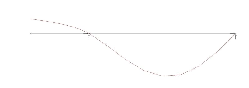
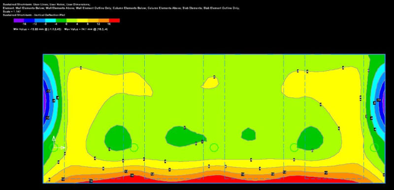
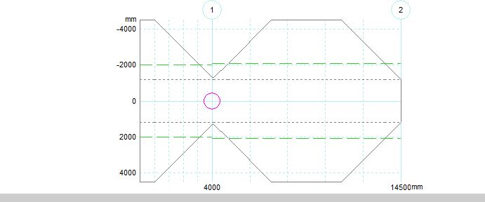
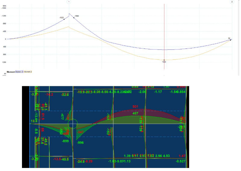
The floorplate is a 4m cantilever, 10.5m back span with a 9m tributary; a 400dp, 2.4m PT band beam with a 180thk PT slab structure has been adopted. Typical office loading of 1.5kPa SDL, 3kPa IL and 2.9kn/m for facade. Adopting the same concrete grades and PT profiles between RAPT and RAM results in the cantilever deflections that greatly differ:
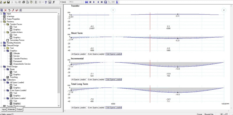
RAPT: Circa 8-9mm
RAM: Circa 16-20mm

I am traditionally a RAPT user so I may be doing something wrong in with my RAM modelling.

Thanks in advance for any help (i'm sure that the "RAM vs RAPT" question has been asked loads of time)!

RAM_export_ovpvtl.jpg
RAPT_export_fvsaok.jpg


Replies continue below

Recommended for you

Gonna preface this by saying I don't have much experience in PT slabs....

IIRC RAPT doesn't do beams for 2-way PT? I did also die a little inside when i noticed that you've set up your latitude and longitude tendons the wrong way around. I can't seem to find the facade loading in the RAM model either (though I think that would make the deflections even worse if they're located on the slab edge?). The main thing I can think of is that because the main span in RAM is properly 2-way in terms of load distribution and tendons, rather than 1-way like rapt, you're getting substantially less deflection there, which could actually be advantageous in terms of rotation at the column helping with the cantilever.

----------------------------------------------------------------------

Why yes, I do in fact have no idea what I'm talking about
 
Thanks for the response JSN - its appreciated!

As a system, it should be relativity one way as it only two points of support. You could argue that the continuous support (away from the column) would pull load from the back-span but after rerunning the RAM model with a support under the beam only it only minimal change to the deflection cantilever. I also re-ran the RAPT run with the tributary reduced to simulate a yield line extent on the beam (accounting for the continuous support and the column) – again within minimal change to the cantilever deflection.
Drilling down on the calcs – it looks like RAM cracks the cantilever section to 0.6 to 0.8 igross at the PT transfer stage – which seems a little weird as the equivalent stress would be minimal?

fyi - the facade loading should be in the RAM model under a separate load case.

RAPT_export_2_t3foz3.jpg
 
You can do it as a 2way beam in RAPT but you have to define the load distribution. Most designers take the conservative option for the band design and assume a 1way distribution of load to the band. It does not make a lot of difference and a 2 way is not correct anyway due to the relative stiffnessof the band direction relative to the slab direction.

For a 10.5m single span with a single 4m cantilever, I would expect the span deflection to be more than the cantilever deflection, which is what RAPT is showing.

RAM appears to be showing much less deflection in the span than the cantilever, which I find hard to believe, but ti would depend on the full loading that I do not know.

To say more I would need to see the RAPT model.

You can always send the RAPT model to me if you are a RAPT user.
 
Multitude of variables here that will dictate the differences between the two softwares.

Instead of trying to match the deflections, how about you first try and match the moment and shear distributions in the bands and slabs (or atleast explain the differences).

Then you can start unpacking all of the load history inputs...
 
Thanks for the response RAPT and Trenno,

Rapt run attached for reference (with the LLR at 1 for comparison to RAM).

This all came about as I completed a concept layout in RAPT and got my Grad to finalise the design who picked up deflection issues in RAM – which doesn’t make sense to me as it’s a relatively balanced system. I did reach out to RAM and they thought it was peculiar that the back-span was deflecting so much in RAPT – which I disagree with – it should and balance the cantilever.

@trenno – BMD and reactions have been reviewed (image attached) and are comparable. This is where we drilled down to the Ig/Ieff values in the LT deflection calcs in RAM. At transfer RAM has a negative deflection of circa 4mm (vs <1mm in RAPT) and the Icr values adopted are <50% (vs uncracked in RAPT) – The RAPT results appear to make a lot more sense to me but now I’m half way down the “RAPT vs RA” rabbit hole and need closure – I’m sure we have done something silly and I’m just not seeing it.
RAPT_export_3_kpv8j4.jpg


The back span effect is even more pronounced because the section is cracked in the back span at the bottom (about 4MPa tension) while the support region and the cantilever are uncracked.

At transfer, it is fully in compression (minimum about 1.3MPa compression). Hard to understand why you would use a cracked inertia!

I can get those sorts of relative deflections between cantilever and back span if you put a column at the end of the back span! But not with the arrangement you have.

Run it in a frame program without any prestress and check the relative deflections you get just for the applied loads. No prestress, cracking, long term effects etc. 2D or 3D, the relative effects should not change that much.
 
Hi GTD_18, it looks like you have a similar workflow to me for design of PT slabs...
I don't have time at the moment for a deep-dive into either of your models, but a quick look highlights some differences between the models that haven't been mentioned yet.

You are comparing a load history analysis result from RAM to RAPT's results - for the same loading conditions I'd expect these to give very similar results.
BUT, you are not looking the same loads. Your RAM model load history has the facade load applied with no load on the backspan for a month prior to the application of loads on the backspan (your temp construction load case is empty).

Also, the anchorage for the beam PT in the RAM model is at 200mm above the soffit (half the beam depth) whereas in RAPT it is at 220mm (geometric centroid of the T-section). An anchorge below the centroid in a T-section is going to be increasing your cantilever deflections as well.

I hope this helps with resolving your inconsistency,


Thanks Dominator,
Apologies for the delay in response - i have been off ill so I didn't have a chance to review the forum in a while.
I updated the comments that you made but with no change to the RAM results. I think i will continue to use RAPT (as i always did) :)

Going back to RAPTs point - a simple 2D frame check illustrates that the back-span balances the cantilever:
Microstran_x0t0p9.jpg


Thanks again
 
That is about what I get in RAPT if there are no concentrated loads on the cantilever and all pin supports. Cantilever up about 1/3 of the downward deflection in the span!
 
Status
Not open for further replies.
Back
Top