Continue to Site

Eng-Tips is the largest engineering community on the Internet

Intelligent Work Forums for Engineering Professionals

  • Congratulations KootK on being selected by the Eng-Tips community for having the most helpful posts in the forums last week. Way to Go!

Random analysis - stress plot 1

Status
Not open for further replies.

ned112

Aerospace
Dec 17, 2012
9
Hi everybody, I hope someone could help me solve a problem I'm having in anlyzing a component.
The component is basically a short mast, with circular section, crimpled to a support, at the other end there are some instruments.

I am performing random analysis through MSC.Random. Then eveluating the PSD response and the stress using the built-in tool of MSC.Random.

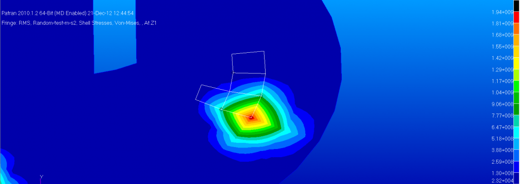
I'm having very strange results though: basically in every test I have performed (many test, with different constraints and different meshing) I realized that the elements where I attach the input acceleration are the most stressed. The problem increases when the mesh becomes smaller and more detailed.
Looking at the acceleration plot response I realized that there is a strong damping effect in the first element, as it absorb a big quantity of energy.
The stresses at the input nodes are incredibly high and unrealistic. (I'm talking of X*10^3 Mpa!! on a component that weight less than 200 grams and it not bigger than 250mm with moderate PSD loading)

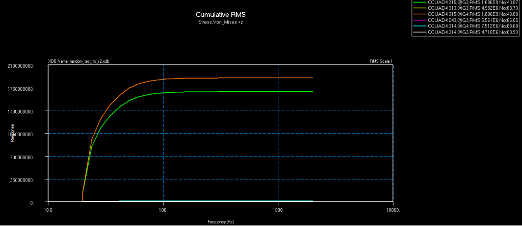
Another strange effect is that plotting the CRMS of the Stress It apperars evident how the biggest part of the stresses is accumulated on the lowest frequency (10-80 Hz), while the hightest PSD inputs are between 50-300 Hz and the first frequency is around 160 Hz.

Basically seems some sorf of effect that tends to concentrate the deformation and so the stresses on the input nodes, but I cannot realy explain why.
I'm attaching some pictures:
Stresses:
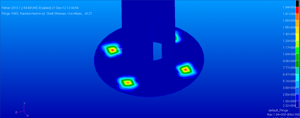
StressVMS_zps75e86f76.png

Details:
StressVMS_2_zps33e0493c.png

CRMS Stress Plot:
StressVMS-CRMS-Linear_zps8251d7ca.png

Another example of a different meshes with even higher results, it seems that the smaller the mesh become the worst are the results!
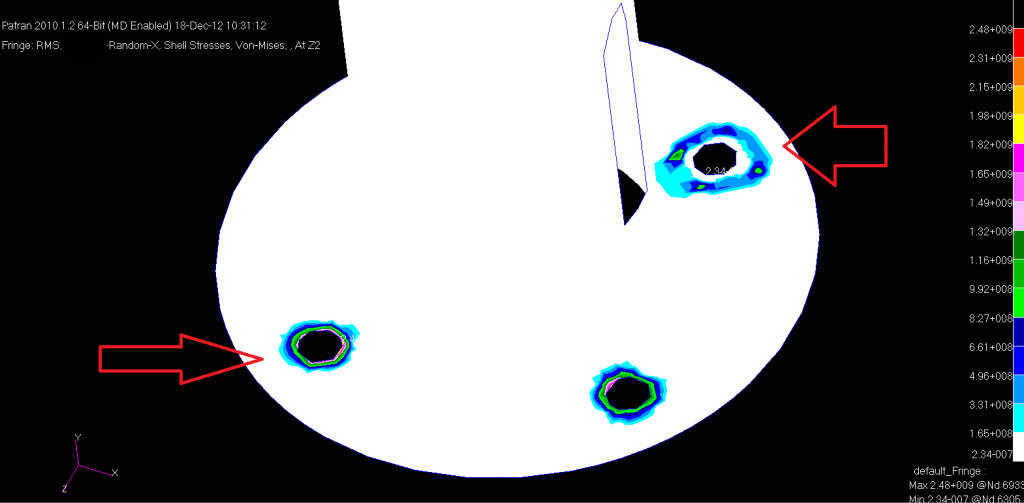
RMS-VM-stress-X_zpsafa8ea5c.png


I thank everybody who will be able to help me!
Ned
 
Replies continue below

Recommended for you

During the holiday I found out what the problem is, or at least what it could be.

I create a test case, with a cilinder + flange and I create the .bdf using MSC.Random of Patran 2010.1.2 and then I run the .bdf on 4 different solver (mine Nastran 2012.1, the one of Nastran 2007 on the pc room of my University, Nastran 2010 and MD Nastran 2.1 of two other professionist I know).
Results: -> 2 sets of different results. Nastran 2010 and 2012.1 provide wrong results but these results are equal. Nastran 2007 and MD Nastran 2.1 provide another set of results, equal, and apparently correct.

Now, I can't really explain this, but I think it may be due to a set of instructions I provide to the solver in the wrong way. Maybe a change in providing the instructions to the solver that happened between the version 2007 and 2010.
I don't really know... any idea??
 
Regarding the discrepency in your results between different MSC Nastran versions. I would attribute this to differences in your .bdf/.dat files.

If you upload your .bdf file(s), I can take a quick look at it.
 
Here is the code of the .bdf as generated by Patran. I even tried to simplify it, but it didn't work. Anyway this one is the standard code generated by patran. I didn't add the model itself (elements, grid nodes).
Code:
$ NASTRAN input file created by the Patran 2010.1.2 64-Bit (MD Enabled)
$ input file translator on January   07, 2013 at 14:45:21.
$ Direct Text Input for Nastran System Cell Section
$ Direct Text Input for File Management Section
$ Delete xdb file before re-running job
ASSIGN dbc='Random_X_standard.xdb',
unit=40 unformated delete
init master(s) $ do not save database
$ Direct Text Input for Executive Control
$
$ Frequency Response Analysis, Modal Formulation, Database
SOL 111
CEND
$ Direct Text Input for Global Case Control Data
$
TITLE = Job Created by Patran Random
ECHO = NONE
RESVEC = NO
LOADSET = 102
SDAMPING = 1
SUBCASE 1
   TITLE=Created by Patran Random
   SUBTITLE=msc_random_base_X
   METHOD = 1
   FREQUENCY = 1
   SPC = 2
   DLOAD = 103
   ACCELERATION(PLOT)=ALL
   SPCFORCES(PLOT)=ALL
   MPCFORCES(PLOT)=ALL
   STRESS(PLOT,BILIN)=ALL
   FORCE(PLOT,BILIN)=ALL
BEGIN BULK
$ Direct Text Input for Bulk Data
$
$ ======================================================================
$ =============== Bulk data cards created by Patran Random ================
$ ============================= Enforced Motion =============================
Param,Enfmotn,ABS
$ ======================================================================
$
$
$ ====================== End of Patran Random Created Cards ===============
$
PARAM    POST    0
PARAM    WTMASS 1.
PARAM    GRDPNT  0
PARAM,NOCOMPS,-1
PARAM   PRTMAXIM YES
FREQ2    1      19.9    2000.1   50
FREQ4    1      19.9    2000.1  .03      5
FREQ     1      20.     50.     300.    2000.
TABDMP1  1       CRIT
        10.     .05     50.     .05     300.    .05     2100.   .05
         ENDT
EIGRL    1      -.1     2000.1           0
$
HERE ARE THE MODEL DESCIRPTION - ELEMENTS, MATERIALS, GRID
$ Loads for Load Case : msc_random_base_X
SPCADD   2       101     102
RLOAD1   105     106                     1               ACCE
LSEQ     102     106     107
SPCD     107     6567    1      1.
RLOAD1   108     109                     1               ACCE
LSEQ     102     109     110
SPCD     110     6568    1      1.
RLOAD1   111     112                     1               ACCE
LSEQ     102     112     113
SPCD     113     6569    1      1.
RLOAD1   114     115                     1               ACCE
LSEQ     102     115     116
SPCD     116     6570    1      1.
DLOAD    103    1.      1.       105    1.       108    1.       111
        1.       114
$ Displacement Constraints of Load Set : msc_random_X_unit_accel.101
SPC1     101     1       6567    6568    6569    6570
$ Displacement Constraints of Load Set : crimpled_RBEs
SPC1     102     123     6567    6568    6569    6570
$ Referenced Dynamic Load Tables
$ Dynamic Load Table : msc_random_Flat_Field
TABLED1  1
        10.     1.      2100.   1.       ENDT
$ Referenced Coordinate Frames
$
$
ENDDATA
Here as it is works well in MD R2.1
 
Any idea?

Note: I cancelled the nodes, points (GRID) and elements list from the bdf to be able to post the bdf on this page.
 
I guess you have used nocomps parameter just to avoid some fatal messages? So, removing it may help to us if is there any formatting error.

What it looks strange to me is SPC1 card. I think you should remove X in ID 102, like this one;
$ Displacement Constraints of Load Set : crimpled_RBEs
SPC1 102 23 6567 6568 6569 6570
 
Hi Kurunta, I tried taking away 1 from SCP1 as you wrote, but doesn't change anything, the code as I wrote it is the same as the one produced by Patran, no change to it. I'am really triyng to understand why... I even tried to wrote manually the .bdf file (for another project) following the Nastran Advanced Dynamic Analysis Guide Chap.8 but I'm having non-realistic results even in that way. It's becoming a little frustrating...
 
Status
Not open for further replies.

Part and Inventory Search

Sponsor