Continue to Site

Eng-Tips is the largest engineering community on the Internet

Intelligent Work Forums for Engineering Professionals

  • Congratulations KootK on being selected by the Eng-Tips community for having the most helpful posts in the forums last week. Way to Go!

Random response analysis - Nastran 1

Status
Not open for further replies.

NastranQ

Automotive
Sep 3, 2007
19
Hello,

This may be a basic question, but I found no obvious answer on the web or the Nastran Dynamic analysis User's guide.

As stated in the Nastran Dynamic analysis user's guide the Random analysis is treated as a data reduction procedure that is applied to the results of a frequency response analysis.


Is there a rule of thumb for selecting the frequency increments for the preceding frequency response analysis?

Let's say I have a structure that has 20 natural frequencies in the 0-1000 Hz range for which I need to perform base excitation using PSD input.
Is it enough to select the natural frequencies? Do we also need to add the input PSD break points? Any other ?

I noticed that the results are sensitive to what frequency increments are selected for solutioning..

Any reply is very appreciated.
Any thoughts?
 
Replies continue below

Recommended for you

It depends on the complexity of your model

with a large model, if you select many frequency steps, your simulation can last "forever", because you will have too many integration points

if your model is simple-ish, it is a compromise between computational cost and results accuracy

if you have a considerably complex model, it is recommended to have as many steps around the natural frequencies as you can, lets say 5 freq. steps around each natural frequency. If you include the natural frequencies, you are catching the peaks, and your integration will be better, therefore better results.

Depending on the size of your model you may find that 5 freq steps spaced aroud each nat. frequency is too much (20x5* model size...=100* model size...)and will have to reduce to 4 or 3 steps, or only nat. frequencies only...
If the simulation time is quick enough, you can gradually increase the freq. steps until you are happy with your results, i.e. until your resutls don't change much when increasing the frequency steps (aim for 5% difference

 
Hi Filipe,

Thank you very much for your reply.
I still don't have a feel for this.
I am currently doing a study on a simple beam structure (hexa meshed)to try and figure out some optimum frequency increments to select.
Also I am comparing the results with Ansys which seems to have a different approach for this analysis.
I will let know the outcome. Maybe you can give me some feedback.

Another issue I have is with the output size (.op2). Actually I am only interested in the maximum RMS stress in the structure, but it looks like regardless of the output options I am using the results file (.op2) always contains 2 sets of results :

1. the stress results at each frequency for the preceding frequency response analysis
2. the PSD stress at each frequency + RMS over the frequencies.
Is there any way to keep only the RMS over the frequencies in the .op2 file?
 
Hi

Yes please let me know. If you want you can send me the beam geometrical characteristics, the material and the load environment and I can provide a quick crosscheck

When requesting the RMS stress output, in your nastran file, use this:
STRESS(SORT2,PLOT,NORPRINT,PHASE,RMS) = ALL
and you will have only the RMS values when importing the op2 file into your postprocessor
then you can check the maximum RMS value and its location
 
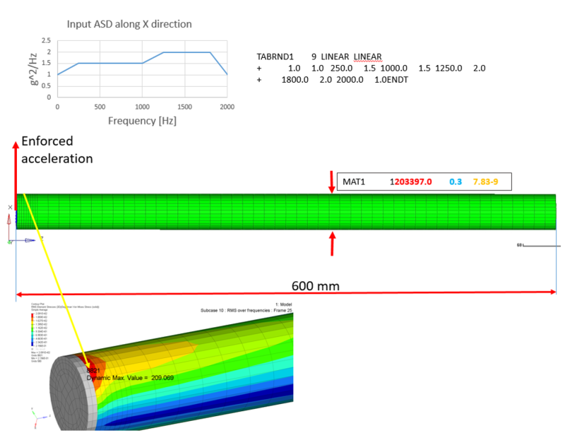
Thanks again. Please see below the problem specs and also the stress results for one of the iterations I am doing. The stress seems to be stabilizing around this value (209 MPa).
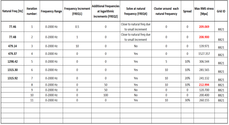
Also in the attached sheet I played with different frequency steps and recorded the max stress results.
Please let me know your opinion.

rnd_szjewa.png
 
Not sure if the attachment went thru. See below..

ttt_lmlq1u.png
 
I guess the material density you provided is not correct. I guess you meant 7.83e-3 instead of 7.83e-9 ?

I don't get you mode #5, what are your boundary conditions? I guess it is fixed at one tip and free at the other, i.e. cantilever beam...?
 
Hi,

I am using tone/mm^3 for the density units. This is why it is 7.83e-9...
The BC's are cantilever beam indeed.
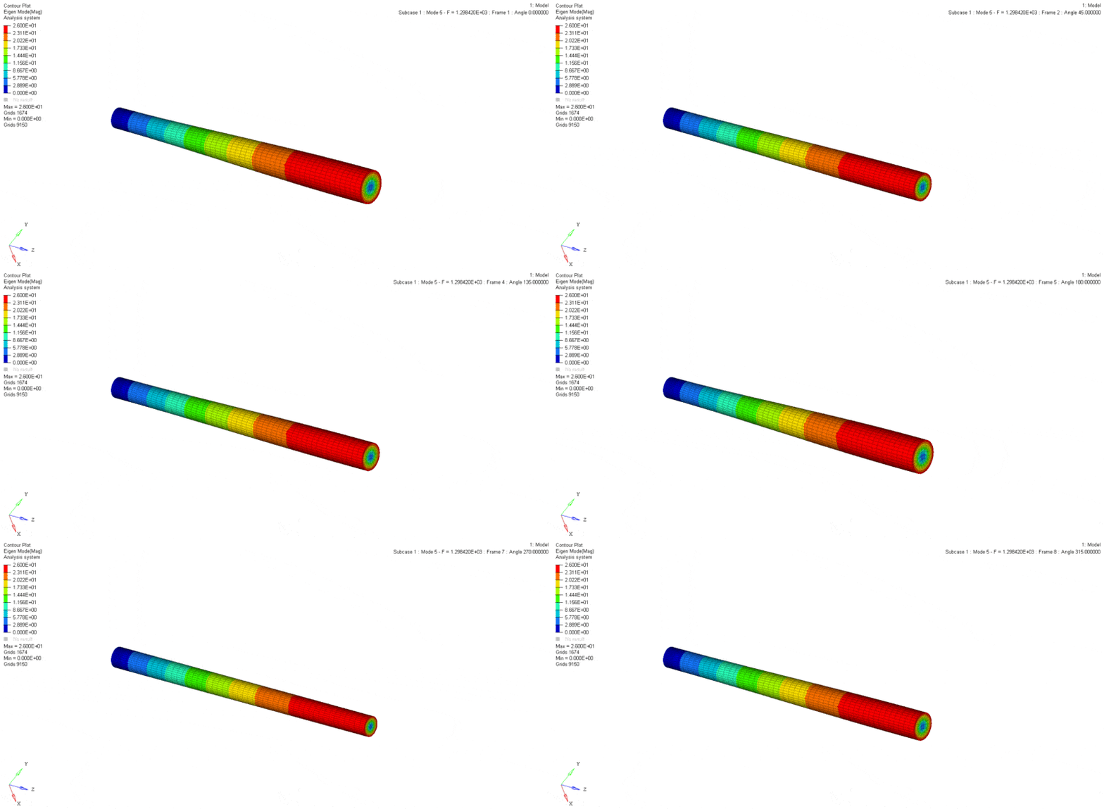
The mode #5 is a torsional mode (see below). Are you using CBEAM/CBAR ? Maybe this is why you are not capturing that mode..
torsional_goszsx.gif
 
Hi,

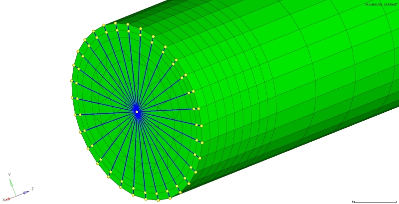
Sorry for the late reply. I am using a RBE2 spider which grabs the nodes highlighted below.
The acceleration is applied at the center node.

image1109_vuotcq.jpg
 
Also I am ignoring the first 2 element rows (near to the spider) when plotting the stress.
 
better to post your bdf/dat file

too much confusion with the units and boundary conditions.. should have asked you this in the first place indeed
 
I am actually running in Optistruct which is very similar to Nastran. (more confusion)
Only the header part is a bit different. I can prepare an equivalent Nastran file.
In the mean time please find attached the Optistruct deck which you can use to see the dimensions and boundary conditions.

 
now, by checking the model, the material units seem consistent with the geometry dimensions and applied load

I did run the random analysis with a different frequency function generated in another preprocessor - see below

FREQ 269.7130369.7293873.5859873.6032377.4589377.4770981.33187+
+ 81.3509485.2048285.22479431.2041431.4025455.1599455.3693479.1157+
+ 479.3361503.0715503.3029527.0272527.26971167.9121183.4091184.042+
+ 1232.7961249.1541249.822 1297.681314.8991315.6021362.5641380.644+
+ 1381.3821427.4481446.3891447.162


With exact same conditions as yours, appart from the frequency function, the maximum RMS stress obtained was 234MPa
in x-direction. if this is your objective I think your results are good enough

comment:
you are enforcing displacement, not acceleration, while your input PSD is in g2/Hz.
With this you have very large von Mises RMS stresses, in the order of GPa...
Replacing enforced displacement by acceleration you have much lower RMS von Mises stresses.

hope it helps
cheers
 
Thank you very much!

Seems to be close to my results. I wonder what preprocessor you are using and also what is the logic it is using to generate the Frequency function? The increments seem to be clustered around the natural frequencies?

Not sure why you say I am enforcing displacement
I am using the below cards:
RLOAD1 7 15 3 0 ACCE
SPCD 15 1 1 9807.
 
OK. Can you please send me your model ? (the one that gives 234 MPa)
 
Status
Not open for further replies.

Part and Inventory Search

Sponsor