Eng-Tips is the largest engineering community on the Internet

Intelligent Work Forums for Engineering Professionals

Ratchet Dismantling and Plate wear

Status
Not open for further replies.

quinor

Civil/Environmental
Dec 18, 2023
4
0
0
US
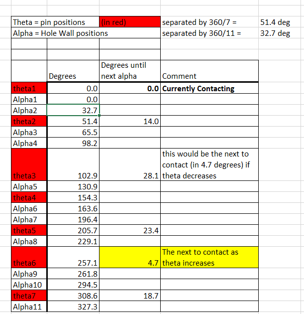
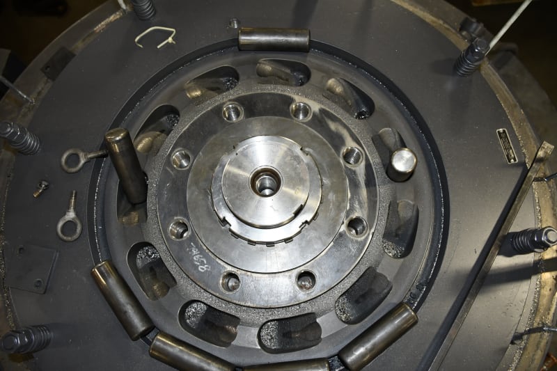
We own 4 of these motors described below. The motors are tripping due to high vibration. Last week we found that the ratchet (NIDEC's design) is coming apart. This ratchet design uses pins to lock the shaft in place to prevent it from backspin.
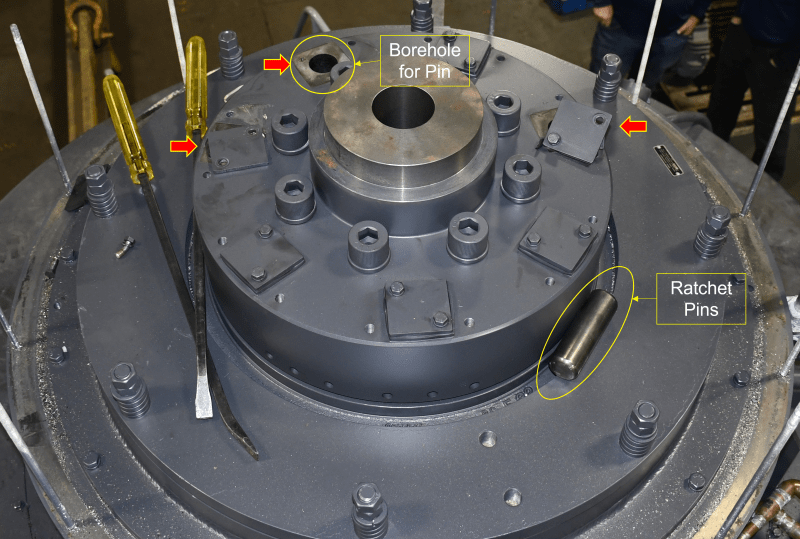
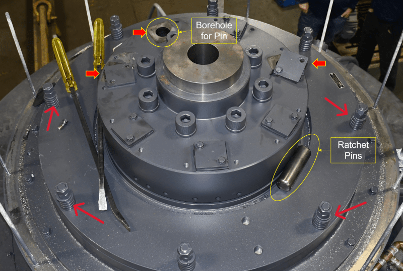
1. Has anyone experienced this failure mode before where pins are pushed out of their boreholes (Image with red arrows and some notes)?
2. Also, if you take a closer look at the unedited image, there is a considerable amount of shavings in the pockets that are supposed to hold the ratchet pins when reversing. The pins will slide in the forward direction until they are held above the resting plate (the one with the pockets) until it coasts down and the pins slide down to engage. The wear damage is from only 9 months of intermittent operation (2 times per day, approx. 6 hours of operation). Has anyone experienced this level of wear?
3. The bottom plate is cast, shouldn't it be from the same material as pins or stronger?

_DSC6628_w4c96u.jpg
EDITED_-_Ratchet_Issues_jplrt5.png


Features:
Horsepower .............. 02500.00~00000.00 ~ KW: 1865
Enclosure ............... WPII
Poles ................... 08~00 ~ RPM: 900~0
Frame Size .............. 9606~PY
Phase/Frequency/Voltage.. 3~060~4160
Winding Type ............ Form Wound
Service Factor .......... 1.15
Insulation Class ........ Class "F" ~ Everseal
Altitude In Feet (Max) .. 3300 Ft.(1000 M)
Ambient In Degree C (Max) +40 C
Efficiency Class ........ Premium Efficiency
Application ............. Vertical Centrifugal Pump
Inverter Duty NEMA MG1 Part 31
Customer Part Number ....
Base Diameter (BD) 50
Flange Mounting on PE (AK) 36
AJ 45.00
BF 1.125
Special "BA" Dimension
Special "H" Dimension
Base Diameter (Inches) ....... 50
Non-Reverse Ratchet
Pricebook Thrust Value (lbs).. 16500
Customer Down Thrust (lbs) ... 46425
Customer Shutoff Thrust (lbs). 73124
Up Thrust (lbs) .............. 4950
Momentary Up Thrust
Inverter Duty Rating Details:
Load Type (Base Hz & Below) .. Variable Torque
Speed Range (Base Hz & Below). 4:1
VFD Service Factor 1.00
"AK" Dimension (Inches).. 36
Shaft Dimensions:~U=5.500 ~ AH/V=11.500
KEYWAY=1.250 ~ ES=9.000
Temperature Rise (Sine Wave): "B" Rise @ 1.0 SF (Resist)
Starting Method ......... Direct-On-Line Start
Duty Cycle .............. Continuous Duty
Sound Pressure Required (dBA) 85 dBa @ 1M Sound Pressure
Load Inertia: 606 ~ Standard Inertia: 41898 LB-FT2
200 % BDT ~ 60 % LRT
Number Of Starts Per Hour: NEMA
Motor Type Code ............ RVEI4
Rotor Inertia (LB-FT²) 3580 LB-FT²
Qty. of Bearings PE (Shaft) 1
Qty. of Bearings SE (OPP) 1
 
Replies continue below

Recommended for you

We had some problems with sliding pin anti-reverse rotation mechanisms on vertical motors, although a slightly different style and a different problem. It was discussed a lot of details (and good input from others) here: thread404-478475

My lessons from that (not necessarily relevant to you): The pins can see a lot of force when they engage during reverse rotation. And the combination of number of pins and number of ratchet steps determines how long an arc reverse rotation can occur before they engage (longer arc means more time to accelerate in reverse direction and therefore more momentum/impulse to absorb when they finally do contact). Also counting on pins to share the load during "simulateous" contact of multiple pins is a dubious proposition since it would require ridiculously tight geometric tolerances to actually achieve simultaneous contact and load sharing.

For your situation, were the pin covers found that way partially dislodged and shown in 2nd photos? And if pin covers were in their proper position (rather than out of position) would they have low enough clearance to the top of the pin to prevent pin from dislodging? If both yes, then first guess maybe the pin cover needs to be held more securely in order to be able to absorb the force from stopping reverse rotation? (the other factors about load sharing and number of pins / steps may play a role as well). Maybe that is all obvious or maybe off base, I'm not sure...

EDIT - And how many steps are there on the ratchet plate below those pins (that plays into the combination which determines maxixumum reverse arc between pins dropping and pins making contact).

We didn't see shavings but we did conclude we needed to start using lubricant on the pins to prevent them from sticking. Were you able to determine which portion which which component was producing the shavings?


electricpete, it was your older thread what motivated me to ask in this forum. I looked at the ratchet in that thread and it intrigue me. Let me start by answering your questions.

1. For your situation, were the pin covers found that way partially dislodged?
Yes, they were found as you see them. The only thing I believe can do that is the pin pushing from inside. Fatigue must have loosened those covers.

2. If pin covers were in their proper position, do they have low enough clearance to the top of the pin to prevent pin dislodging?
By the looks of it, they do. Pins are approx. 6 inches long. When the pin is in the top position of the pocket, the space is approximately 1 inch. When the pin is inside the pocket, the space is approx. 3 inches.

3. If both yes, then first guess maybe the pin cover needs to be held more securely in order to be able to absorb the force from stopping reverse rotation?
I agree but again, the OEM claims this never happened to them. They also claim that their motor frame is well established (15+ yrs). I have my doubts of course. But let's say they are correct; it must have been they changed something in their design OR this is a problem of workmanship. Currently, the 4 motors are new and two failed in the same fashion. The other two motors are not commissioned yet.​

Say, what is your opinion on the wear metal shavings?
Did the lubricant solve your wear problem?
Did you use grease? How often you add the grease in your ratchet example?
I looked at the image you posted in the thread you referenced earlier, and the ratchet plate looks like fabricated steel and not cast. Is it fabricated steel or Cast?
 
Did the lubricant solve your wear problem?
Did you use grease? How often you add the grease in your ratchet example?
We use molybdenum disulfide spray. We put it on during motor refurbishment and then every 2 years. We have pretty easy access from the top after removing a single cover. Then with manual rotation in the forward direction pins protrude above the top where we can pull them out to spray and put them back in.

We have had no problems since but I think it is too soon to say that we've solved anything.

I looked at the image you posted in the thread you referenced earlier, and the ratchet plate looks like fabricated steel and not cast. Is it fabricated steel or Cast?
I don't know for sure. My guess is that fabricated would be what I would expect for this application. And the damage to the ramp looks like ductile deformation, I picture cast would be more likely to have brittle failure, wouldn't it? (I'm an EE, my materials knowledge is pretty limited)


Say, what is your opinion on the wear metal shavings?
In our case we had a few metal shavings but they appeared to be related to the locations where pins jammed into the ramps. The scenario I envision is that original problem was pins not fully dropping, then causing ramp damage and shavings during subsequent start. The lubricant was an attempt to make sure the pins would drop freely. For your case I'd guess the shavings might likewise be consequential damage after the pins jammed hard into the covers and then slid past them.

I agree but again, the OEM claims this never happened to them. They also claim that their motor frame is well established (15+ yrs). I have my doubts of course. But let's say they are correct; it must have been they changed something in their design OR this is a problem of workmanship. Currently, the 4 motors are new and two failed in the same fashion. The other two motors are not commissioned yet.
I don't know how much engineering goes into specifying that anti-rotation device. But it stands to reason that different fluid applications would make different demands on that anti-reverse-rotation device. For example, it may be that your pump sees a particularly high reverse dp after it is stopped.
 
Did you notice the bent and broken bolts for the covers? The pins are impacting the covers hard. This is not a fatigue problem.

You mentioned NIDEC. This is from their website.
NIDEC said:
Another offered feature is Impact Dampening on size 5000 frame and larger. This feature reduces the shock when the ball engages the stationary ratchet. This is accomplished by using a large "C" spring, bonded brake lining on the stationary ratchet, and a dampener plate that is spring loaded. On impact, the "C" spring dissipates the energy and reduces shock.

This must be relevant to those springs.
 
Apologies if these are odd questions.

I assume the normal orientation of the pins is vertical?

I counted 7 pins, but 11 holes in the bottom plate.

How does that work? only one pin ever engages?

The filings I think come from where the pins are making their own groove in the rather vicious taper out of the hole. You can see where the pins have created a semi circular groove at the top of the ratchet hole.

So what was the failure exactly? One pin had come out and hence the system was unbalanced?

Remember - More details = better answers
Also: If you get a response it's polite to respond to it.
 
May be a dumb question (coming, as it is, from an EE) - but is the thrust bearing installed in the correct orientation to properly limit upthrust? In a similar vein - has it been determined (by actual measurement) which direction the continuous and momentary thrust occurs? Does the thrust direction change with rotation?

Converting energy to motion for more than half a century
 
I can only add that sizing of backstop clutch assemblies is fraught with guesstimation due to the sudden engagement of the clutch and the rotating inertia of the rest of the rotating system. Motor-mounted backstops only have so much capacity.

In my one experience with a motor-mounted one-way clutch, they kept blowing up and we had to put a separate device on a free shaft end elsewhere in the system, and this is what it took to mount a suitably large clutch.
 
I don't see signs of the brake being overloaded. If that were the case I would expect damage on the side of the hole opposite the ramp and possibly on the pins as well.

Is it possible the rotor experienced a reversal of thrust that caused to to lift and push the pins through their cover plates?
 
Thank you everyone for your help in brainstorming this failure mode. You should know that for years I have monitored forums similar to this but never posted a question. I find it fascinating and helpful to discuss and brainstorm with engineering colleagues. Again, thank you all.

TugboatEng (Marine/Ocean): There is no evidence to suggest that the pins pushed through the caps from one single blow to the cap. That would have left behind damage visible in the threads, the bores and the fasteners (by elongation of some form). However, in that is not the case. It is more likely than not that the fasteners came lose because they were never properly preloaded. That will qualify this mechanism as fatigue. Once the plate was able to move, the impact of the pin would have exerted a force for which the fastener was not designed, bending the fastener with every impact. Again, one of the two fasteners must have come completely lose first, then the second fasteners would have loaded by the level arm advantage that the plate has over the only fastener still in place.

LittleInch (Petroleum): You are correct, when you lose one pin, the ratchet becomes unbalanced which is reflecting as a 1.08ips vibration affecting the entire motor. Each pin weights 2.64lbs. Almost forget, according to OEM, the ratio of pins to rams is to ensure that one pin locks in place. What I found yesterday is that only one pin engages, period.

Gr8blu (Electrical): The bearing is properly installed but it is not the bearing which limits upthrust in this motor. There are other components that make sure of that, or so I have been told. I have also been told that there is a balance that must exist between the load from mass and the potential upthrust. However, if you take a closer look at the pictures, you will notice that thrust is irrelevant in this case. The pins are free to move in their cavity. The assembly can move up and down all they want, and the pin will move independent of any upthrust.

geesaman.d (Mechanical): I agree it is fraught, but I also see there is potential. In my experience over the years is that there is a lack of engineering in the industry due to multiple factors, too many to discuss here. Concerning the capacity, there is no evidence to suggest the pockets, or the pins have been engaged. The damage you see is the result of forward motion. This OEM claims this ratchet can withstand the worst-case scenario of full reverse torque which is, wait for it, "1.38 times the forward speed and torque", Yikes!!! [surprise]. The current impeller, if allowed to free spin, it can max out at 1250 RPM on a system rated to max out at 900 RPM. This brings us to your next statement, free shaft. I believe you are referring to free spinning. Out front we have the problem of components withstanding that speed. Everything inside the motor is rated and, in this case, at 1250rpm will rip it apart. There is also the other side of the coin, power generation. There is a god potential that the motor will turn into a generator which will destroy other equipment. We discuss this last subject yesterday and the outcome does not look good. Are you experiencing electrical issues when your unit's backspin freely?

TugboatEng (Marine/Ocean): I agree! Concerning the question and if I understand you correctly, the answer would be no. The bore hole that houses the pins are longer than the pins. There is simply no way the pins can be pushed against the covers by means of upthrust or downthrust. In my humble opinion, the pins are energized with enough force to either (1) break through the caps, which there is no evidence to suggest such mechanism is taking place, or (2) the pins are impacting the caps so much, so often and with enough force that the vibration transferred to the caps loosen the fasteners. Split washers are not a good method to prevent fasteners coming lose. I recommend NOR-LOCK washers. check them out and you will understand why. Also, it is not practical to use rubber between metal surfaces like these. They will simply have a hard time achieving preload in those fasteners. When I asked which torque value they used during assembly, I found that they did not have one to speak off. Does that even make sense? [mad]


MintJulep (Mechanical) I almost forget about your question, and I don't have an answer yet. All I can guess at this time is that the plate is not grooved in the underside, so the designer expects it to move to some degree. For whatever reason he did not want it to have a tight fit either. Also, below that plate lies the oil reservoir. It may be the designer was trying to prevent a blowout so he is trying to prevent the plate from creating a seal by allowing it to move but I am not sure oil will evaporate in such a way. Unless the designer was thinking about overfilling, which I guarantee you, the oil will leak out through other means. It just happens that the installers recently overfill one of the systems with oil and the oil leaked down the shaft. Could it be for vibration dampening?
 
LittleInch said:
I counted 7 pins, but 11 holes in the bottom plate.
How does that work? only one pin ever engages?
Yes it would result in only one pin engaging. I believe the objective of that configuration is to minimize the momentum at time of impact by minimizing the worst case possible arc the rotor can travel in reverse direction before contacting in order to minimize acceleration time before contacting. With 7 rotating pins and 11 stationary holes, the furthest the rotor can travel between contact points is 4.7 degrees = 360/7/11 (assumes the pins and holes are collapsed to a point for simpler math, and also neglecting pin dropping time for simpler math). in contrast if you had 7 pins and 14 holes, 2 pins would take the load but the arc of reverse rotation could be 25 degrees = 360/14. That's more than 5 times as much 4.7 degree arc of the 7/11 configuration. I believe those 7/11 numbers were intentionally selected in this way to minimize that worst case acceleration arc.

Screenshot_2023-12-20_155633_b3puu7.gif


In the anti-rotation device on my motor, there was no shock absorbing capability, it seems very unrealistic in that case to assume that more than one pin could absorb the load (the distance travelled between the first pin contacting and rotor stopping is negligible or on the order of the tolerances associated with these parts). However in the op's motor for this thread, there is a degree of shock absorbing capability then the rotor might travel further between impact and stopping and the prospects for sharing load seem better. These two designs seem backwards from what we might expect (it was my motor with 6 rotating pins 12 stationary steps where the designer seems to have intended to share load even though no shock absorption, while op's motor with 7 rotating pins and 11 stationary holes does not attempt to share even though there is shock absorption).
 
So I guess the shock absorption feature is supposed to be that the pin lifts up and hits the pin cover which lifts up that whole center assembly which compresses the springs of those bolts. I guess it might be worth to try to manually lift that center assembly up to check for any binding. I'm not sure how you would lift it, but if it you apply force at one point on the circumference (like by prying at the joint) that could mimmick the behavior where a pin hits at one location first (rather than applying equal pressure around the circumference) which could tilt/cock things. If that piece binds (restrained by something other than the spring) that could increase stress on the pin covers during reverese rotation. I'm not saying it's likely, just one thing to look at, if it can be easily checked.

edit, might as well check for any signs that pins are prone to sticking and not dropping. if one pin didn't drop, that means the rotor is traveling faster when the next pin does drop
 
Those gaskets under the covers for the pins are way too squishy looking to be part of any mechanical connection. Heck, they're way to squishy for any application. I would toss them and use a gasket maker of your choice.
 
actually, I need to backtrack on something. What makes the pins go up during reverse rotation. it seems to be expected based on the design of the shock absorbers and maybe the pin covers. in our motor, the pin drops during reverse rotation and raises during forward rotation (pushed up by the ramp when started in the forward direction). are the holes that the pins ride within at an angle from vertical? (do you have a photo of them?)
 
What does this thing sound like when running normally?

What RPM does the motor run at for your operation?

It looks like the pins drop and engage the ramped slots by gravity, and are pushed up by the ramp.

If that's correct, then wear on the ramps would certainly be expected.

Is there some feature that's intended to hold the pins up during forward rotation?

I'll ask again what those springs I noted are supposed to do?

Depending on the clearance, pins sliding in a closed pocket will create pressure at the closed end - exacerbated if there is any lubricant to work as a seal.
 
The pins should not contact the ratchet plate during normal running. The ramps kick the pins up into their bores and centrifugal force (yes, it's a simplification) holds them there until the speed is lower enough for the pins to drop into the ratchet plate.

I have recently had a similar situation with segmented ring carbon seals. The shaft is meant to push them to a position where they barely touch and friction from ball plungers holds it in place. In our case the friction wasn't sufficient and the seal dropped and rode on the shaft.
 
electricpete said:
actually, I need to backtrack on something. What makes the pins go up during reverse rotation. it seems to be expected based on the design of the shock absorbers and maybe the pin covers. in our motor, the pin drops during reverse rotation and raises during forward rotation (pushed up by the ramp when started in the forward direction). are the holes that the pins ride within at an angle from vertical? (do you have a photo of them?)
Now I see my question was already answered if I was reading closer
quinor said:
There is no evidence to suggest that the pins pushed through the caps from one single blow to the cap. That would have left behind damage visible in the threads, the bores and the fasteners (by elongation of some form). However, in that is not the case. It is more likely than not that the fasteners came lose because they were never properly preloaded. That will qualify this mechanism as fatigue. Once the plate was able to move, the impact of the pin would have exerted a force for which the fastener was not designed, bending the fastener with every impact. Again, one of the two fasteners must have come completely lose first, then the second fasteners would have loaded by the level arm advantage that the plate has over the only fastener still in place.
Sorry, my responses in this thread have been carrying the ill-founded idea that somehow the pins would push up during reverse rotation. That's not the way ours works and there's no logic to that to my knowledge. I was steered that way by an initial interpretation of the shock absorbing mechanism which looked like it was designed to absorb an upward force from pins onto the top plates. I don't know exactly how the shock absorber works, but it's probably not that.

I apologize that I have been vocally projecting an incorrect understanding of this device into your thread.

For my own benefit (not to solve your problem) I would be mildly curious if you have photos of the holes in which the pins ride or an explanation of how the shock absorber mechanism works.
 
I'll answer those based on our anti-rotation device.
MintJulep said:
It looks like the pins drop and engage the ramped slots by gravity, and are pushed up by the ramp.
Yup, that's the way ours works (I'm not the op)
MintJulep said:
If that's correct, then wear on the ramps would certainly be expected.
Yup, the wear looks expected (I'm not the op). And there is no sign of trauma from stopping reverse rotation on the side opposite the ramp or the pins (in spite of my earlier comments about trauma from stopping reverse rotation)
MintJulep said:
Is there some feature that's intended to hold the pins up during forward rotation?
My understanding is same as TugBoat's - after the pin is lifted by the ramp during start, then during running the centrifugal force pushes it against the side of the hole where it is held by friction
MintJulep said:
What does this thing sound like when running normally?
We have a variety of anti reverse rotation devices and they are all quiet while running in steady state (we do have some with hinged pawls rather than pins and those make a clicking noise but only during coastdown just before the motor stops).

I agree that if op's has noise coming from anti-reverse rotation device while running that could be a clue of something.
MintJulep said:
Depending on the clearance, pins sliding in a closed pocket will create pressure at the closed end - exacerbated if there is any lubricant to work as a seal.
For ours (not the op) when we finally started lubricating we selected a dry lubricant (molybdenum disulfide) in part to avoid those types of effects. But the consequences of pin not dropping are that the next pin sees more trauma, which doesn't look like what happened to op.
MintJulep said:
I'll ask again what those springs I noted are supposed to do?
good question
 
Status
Not open for further replies.
Back
Top