Continue to Site

Eng-Tips is the largest engineering community on the Internet

Intelligent Work Forums for Engineering Professionals

  • Congratulations SDETERS on being selected by the Eng-Tips community for having the most helpful posts in the forums last week. Way to Go!

Rating a Shear Connection using Allowable Stress 2

Status
Not open for further replies.

AK4S

Structural
Jan 2, 2015
98
Need some advice from any Bridge Rating Engineers.
I am rating an existing bridge (4 Simple spans,rolled steel beams with a noncomposite concrete deck) which has a Shear connection (Web Splice plate only. No splice connection on the flanges) on the beams of one of the interior spans. It looks to be a construction error where the pier was off by few feet, so they added a Shear connection on the original beam length to make it work. The splice is located close to the support (3ft away from support on a 74ft beam span), so the behavior can be assumed to be as 2-Span continuous with a hinge at the splice location.
Untitled_lhboji.jpg


I analyzed and rated the beams using AASHTOWare. The Shear Forces at the hinge for various load conditions can be obtained from AASHTOWare and used to rate this Shear connection for:
► Connection Bolts in Shear and Bearing
► Flexural Yielding and Flexural Rupture of the Connection Plate due to the Eccentric moment from the applied Shear force
► Shear Yielding and Shear Rupture of the Connection Plate
► Block Shear and Tension Fracture of the Connection Plate

I could not find any examples using AASHTO Std Specs for Highway Bridges or in the MBE(Manual for Bridge Evaluation) to evaluate this connection using Allowable Stress (ASR).
Any suggestions or examples I could refer? I can get the necessary allowable stresses for plate and bolts from the MBE but not sure about the equations to be used to evaluate stresses due to the loads.

The bridge was originally designed using ASD and per State DOT's guideline we need to rate it using Allowable Stress.

Alternatively (Not the preferred option to avoid mixing different code provisions) I am familiar with evaluating the connection using AISC provisions, however I am not sure on how to consider the effects of mixing load factors and varying allowable stresses when mixing the two codes for evaluation. Any suggestions?
 
Replies continue below

Recommended for you

wiktor said:
...the splice is located at or near zero DL moment.

Not in this case, unless that span is less than 15' long. The uniform load contraflexure point for 2 continuous equal spans is about the quarter point of the span.

Designing the girder with the connection assumed to carry only shear is the conservative approach for the girder. For the connection design, the assumption of it being able to form a plastic hinge must be verified. If the bolts shear or tear out of the plates, or any of the plates reach the fracture limit before the full plastic moment of the splice plates is achieved, the capacity of the girder at the point of the connection should be limited to the moment capacity of the controlling feature of the connection.


Rod Smith, P.E., The artist formerly known as HotRod10
 
@BridgeSmith: Looks like I need to go with hand-calcs for the connection. Any references you can suggest for AASHTO Allowable Stress design? Specifically for Shear Yielding/Shear Rupture/Block Shear and Tension Fracture of the Connection Plate. AISC has defined equations in ASD, cannot see them in AASHTO.


@wiktor: Thanks for introducing me to Gerber beams, Good to know.
In my case I referred them as potential construction error (not design). As mentioned earlier, this splice condition did not look like something designed on purpose. All other spans are simple span 74ft. Only one pier is off by 3ft. Also, the original bridge plans did not show this splice connection.
In field, the bottom flange of the two beams at this connection also have fabricated holes for typical anchor connection, indicating that these beams were originally intended to sit on the piers (similar to the other spans).
 
@STrctPono: yes, I am not sure of the internal workings. To confirm that the program is handling the stiffness change correctly, I should verify the results using another analysis.
 
I'm not sure how you would handle it as an ASR; presumably you would use the nominal moments and shears, and compare to the allowable stresses for the bolts in shear and the plates in yielding and fracture. It's been a long time since I did any ASD, so I'm not sure on any of that, especially the net section fracture, which I don't remember ever seeing checked in the little bit of ASD I have done.

You might contact whoever handles bridge ratings at your state DOT, and ask how it should be done. They may make an exception in this case and allow LFR or LRFR, since it's preferred by the feds to do ratings strictly using the AASHTO provisions. As I said, we don't do ASR, even if it was designed ASD.


Rod Smith, P.E., The artist formerly known as HotRod10
 
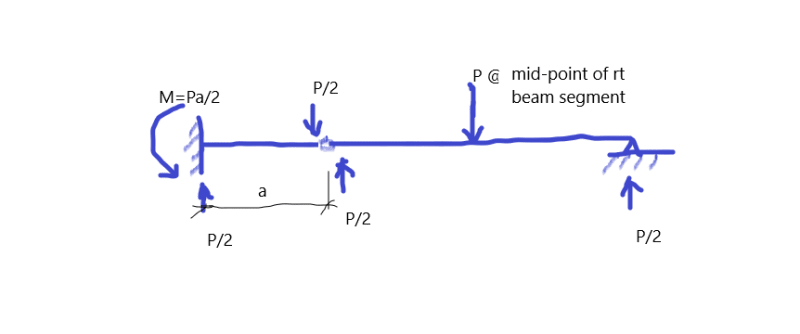
Conventional design example.

moment_td5eyg.png


I would design the link (plate & bolts) for V=P/2, M=Pd/2, d is the distance between the geometric centers of the bolt groups
 
wiktor’s post reminded me; AISC has an old publication on design of cantilevered Gerber beams. My initial thought yesterday, it was a hinge purposely introduced, although a bit odd to have one hinge in a span and not two. I think it’s transferring some moment through the plate but it may be easier
to just treat it like a bracket.
 
Can you explain the difficulty you're encountering with Allowable Stress Rating a little more? Is it just tracking down the right allowable stress for the failure modes you mentioned? Otherwise, if you can determine the capacity through allowable stresses from MBE and force effects through one of the analysis methods mentioned above, your rating is just going to be (Capacity in Failure Mode - Dead Load Effect)/(Live Load Effect)? If they have tension-equivalent allowables (yielding of gross section etc...), can you just use (tension allowable)*SQRT(3)/3 [from von mises]? Depending on the complicating factor, you may find useful information in a code like AREMA, which still commonly uses ASD for steel design.

Do you know what kind of bolts were used?
 
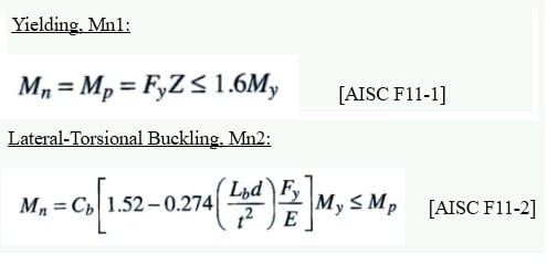
@jrw501: I was looking for references similar to AISC/AASHTO LRFD specs, for example the below equations from AISC to calculate the nominal flexural strength of the connection plate.
Untitled_fwfxtt.jpg

Also listed in AASHTO LRFD Spec. 6.12.2.2.7.

I guess, I could still use these equations for calculation and use allowable stresses obtained from MBE for the Inventory and Operating Conditions.
 
I would recommend starting with applying the plastic moment capacity of the splice plates (Fy*Z) to the bolts and bolt holes, to verify the plastic hinging mechanism would develop before the bolts shear or tear out of the holes.

If the gap between the girder sections is as wide as your sketch shows, it seems fairly obvious there was supposed to be a double bearing pier supporting the ends of the 2 simple-span girders. This was someone's fix for a screw-up in placing the pier. As such, you can assume nothing about the design (or lack of design) for the connection.

I would have to go over every aspect of the connection, every possible failure mode, ensuring that yielding of the splice plates was the controlling failure mode by a comfortable margin, before assuming it will act as a hinge. Barring that, I would rate the bridge using the moment + shear capacity of the controlling aspect of the connection against the applied moment and shear at the splice, and moment due to eccentricity of the shear.


Rod Smith, P.E., The artist formerly known as HotRod10
 
Status
Not open for further replies.

Part and Inventory Search

Sponsor