ArturoMS
Structural
- Apr 19, 2024
- 2
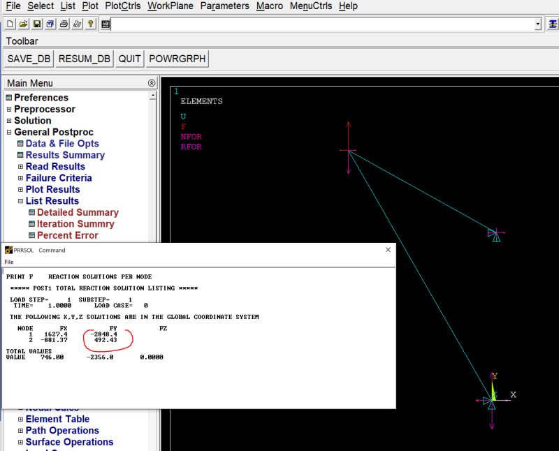
I am undergoing through a situation similar to the one discussed in thread2-478490. As hand calc results I obtained for a typical shear joint with eccentric loading cannot be recreated using non-rigid bodies in mechanical, I am now trying to follow the approach proposed in such thread. However, I have been unsuccessful since I cannot figure out how to create the RBE3 constrain equations with the RBE3 command. I get a warning saying the RBE3 command is ignored since the dependent nodes 1 & 2 are colinear, which seems to be true and also a requirement for the RBE3 command to work.
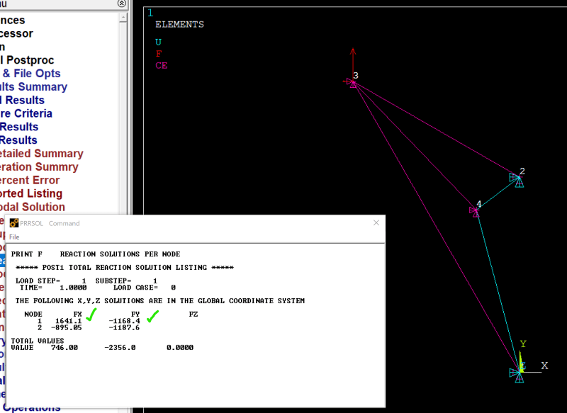
Also, even though the reactions from the apdl model satisfy equilibrium, the vertical reactions are dissimilar and inconsistent with the hand calc results based on equal distribution of the vertical load Fy for rigid bodies.
Is there a way you can think to built the constrain equations using RBE3 command for this specific geometry? My hope is that using RBE3 constrains, the vertical load will be distributed equally at the nodes 1 & 2 displacement BC's.

/PREP7
/SHEAR JOINT ECCENTRIC LOAD
ANTYPE,STATIC ! STATIC ANALYSIS
ET,1,LINK180
SECTYPE,1,LINK
SECDATA,0.1
MP,EX,1,30E6
MP,ALPX,1,70E-7
TREF,70 ! REFERENCE TEMPERATURE
N,1,0,0 ! DEFINE NODES AND ELEMENTS
N,2,0.05,1.8
N,3,-1.534,2.685
E,1,3
E,2,3
NSEL
RBE3,3,ALL,ALL
D,1,UX,,,2,,UY ! BOUNDARY CONDITIONS AND LOADING
F,3,FY,2356
F,3,FX,-746
BFUNIF,TEMP,80 ! UNIFORM TEMPERATURE (TREF+10)
FINISH
/SOLU
OUTPR,BASIC,1
OUTPR,NLOAD,1
NSUBST,1
SOLVE
FINISH
Also, even though the reactions from the apdl model satisfy equilibrium, the vertical reactions are dissimilar and inconsistent with the hand calc results based on equal distribution of the vertical load Fy for rigid bodies.
Is there a way you can think to built the constrain equations using RBE3 command for this specific geometry? My hope is that using RBE3 constrains, the vertical load will be distributed equally at the nodes 1 & 2 displacement BC's.

/PREP7
/SHEAR JOINT ECCENTRIC LOAD
ANTYPE,STATIC ! STATIC ANALYSIS
ET,1,LINK180
SECTYPE,1,LINK
SECDATA,0.1
MP,EX,1,30E6
MP,ALPX,1,70E-7
TREF,70 ! REFERENCE TEMPERATURE
N,1,0,0 ! DEFINE NODES AND ELEMENTS
N,2,0.05,1.8
N,3,-1.534,2.685
E,1,3
E,2,3
NSEL
RBE3,3,ALL,ALL
D,1,UX,,,2,,UY ! BOUNDARY CONDITIONS AND LOADING
F,3,FY,2356
F,3,FX,-746
BFUNIF,TEMP,80 ! UNIFORM TEMPERATURE (TREF+10)
FINISH
/SOLU
OUTPR,BASIC,1
OUTPR,NLOAD,1
NSUBST,1
SOLVE
FINISH

