Continue to Site

Eng-Tips is the largest engineering community on the Internet

Intelligent Work Forums for Engineering Professionals

  • Congratulations waross on being selected by the Eng-Tips community for having the most helpful posts in the forums last week. Way to Go!

RC beam detailing 2

Status
Not open for further replies.

Hende

Civil/Environmental
Sep 29, 2015
3
Hello Everyone,

Can anyone explain the following beam schedule? I cannot interpret some of the abbreviations used in the table specifically the headings.
Tie_beam_Schedule_hdlxvi.gif
 
Replies continue below

Recommended for you

I don't know which "abbreviations" you are having trouble interpreting, but in order to understand the schedule, you need the beam details which go with the schedule. That should explain what an "A1", "A2", etc. bar looks like and where it applies.
 
Hende - When reinforcing steel is shipped to a jobsite identical bars are often grouped together and tagged so that the contractor can identify them. Markings on the tags are in accordance with the rebar fabricator's drawing practices (not the engineer's drawings). The fabricator's shop drawings identify where each of the tagged bars are used. The attached schedule, including the nomenclature, looks exactly like what I would expect to see on the fabricator's shop drawings.

[idea]
[r2d2]
 
SRE,
I don't think so. This looks to me more like a beam schedule on a design drawing. A "T16" just designates the size and grade of the bar, not the length.
 
For proper understanding, this beam schedule must be accompanied by a typical long section (& probably a few cross-sections) of beam, indicating location of various type of longitudinal bars (referred by marks A1, A2, B, D1, D2 etc in the Table Headings) and stirrups (marked by letters G, H and J, in the Table).

A good structural engineer is often a blessing for others.
 
I agree with Hokie here.

here must be a Standard Beam Reinforcing Placement Detail that will answer all your questions, otherwise, the contractor is left as out in the cold as you are right now, and the project becomes unbuildable, let alone un-permittable.

Mike McCann, PE, SE (WA)


Thanks a lot for your kind answers. What does exactly lacer bars EF. mean in the last column? I have the whole set of drawing, but it doesn't include longitudinal and sectional view of the beams.
 
Hende - The "lacer bars" that I am familiar with are horizontal ties, around the perimeter of a footing. They are used to confine the concrete horizontally. They do have other uses, such as in certain slabs supported by beams. As your rebar schedule indicates, I would not expect to see them is a typical beam. "EF" is the usual abbreviation for "each face".

[idea]
[r2d2]
 
I agree with SRE that "lacer bars" are side face reinforcement, but your schedule doesn't show any of these. But in order to understand the beams, you must have details. Do the documents refer to some type of standard? If you can't figure this out, you need to ask the design engineer.
 
Please, have a look at this table which includes lacer bars!
Lacer_bars_vcofdk.gif


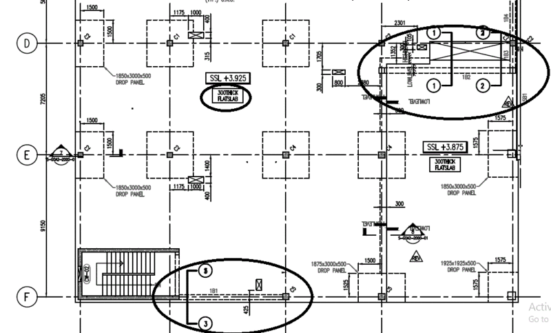
The slab is flat slab and at some places there are beams within the slab! look at the floor plan which shows the location of the beams..

Question_1_sections_1_2_3_y1qz6v.gif
 
OK, the plan helps. The 750 and 825 deep beams have T10-150 side face longitudinal bars, which is appropriate. The top, bottom, and shear reinforcement are also shown. However, you apparently don't have anything which defines the length of bars, lap lengths, hook details, stirrup types, etc. The specified hanger bars are also a mystery, as I don't see how hanger bars would apply with those beams. Instead of asking us for more advice, you really should be asking the design engineer.
 
Status
Not open for further replies.

Part and Inventory Search

Sponsor