Eng-Tips is the largest engineering community on the Internet

Intelligent Work Forums for Engineering Professionals

RC Core Wall 2

Status
Not open for further replies.

MIStructE_IRE

Structural
Sep 23, 2018
816
0
0
IE
Hi,

I have a 7 storey RC frame and am getting 215mm thick RC Core walls to work within the lift/staircores to provide lateral stability and take some vertical too.

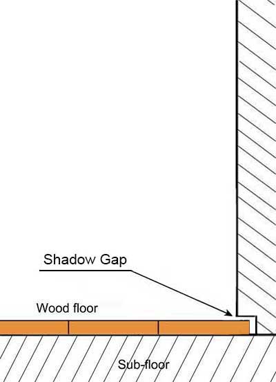
The client however now wants a 15mm x 15mm recess (shadow gap) at the top of the walls each side where they join the slabs. This reduces my wall thickness to 185mm at the interface and of course compromises cover. I’m OK with direct stress on the 185mm wide section.

Is there a typical way round this to overcome cover issues? It seems a shame to add 30mm to the entire wall thickness to accommodate this tiny detail. Presumably I could crank the bars inwards just before this interface? Wall/slab joints will be pinned simple supports anyway.
 
Replies continue below

Recommended for you

I wouldn't crank any of the vertical reinforcement, that's just a poor detail overall and creates difficulties on site, bars want to straighten under load and can pop the concrete off. Only practical way I've dealt with architectural recesses and rebates (typically in precast panels) is to suck it up and add the extra concrete and treat it as non structural essentially.
 
Curious. Can you sketch or further describe this recess? I'm not sure that I get it. It occurs, at each floor just beneath the slab? What is the purpose?

OP said:
Presumably I could crank the bars inwards just before this interface? Wall/slab joints will be pinned simple supports anyway.

Meh. It sounds like a bit of a construction headache (zones especially) but I'm somewhat open to this. For bar tension, which surely governs, the the bar straightening outside of the slab thickness probably causes the bars to pull together rather than spall out. You'd have to nail the location of the upper bend to keep that within the slab thickness though. In compression, you'd definitely create a tendency to spall at the bends but maybe we're okay with that in an extreme/unlikely event. This is probably an IRE project so I don't imagine you're dealing with reversing excursions into the plastic range. And, even if you were, the effect of that would surely be more prominent near the mid height of the wall than at the braced points.

Another option might be to use generous length, non-contact dowels to transition from bars above to bars below. Stuff them in the middle of the wall for all the difference it makes. This may also be a construction hassle though and, depending on the setup, may have you worrying about wet setting etc.


Would the capacity be inadequate if you just shifted the reinforcing that 15mm to maintain the cover at the recesses and had that much extra cover for the remainder of the wall? If so, could you increase the reinforcing area to compensate?
 
"Another option might be to use generous length, non-contact dowels to transition from bars above to bars below... This may also be a construction hassle though and, depending on the setup, may have you worrying about wet setting etc."

One note on this: 15mm is less than the diameter of a #5 bar, so if the quality control is adequate, it should be possible to detail the dowel bars in contact, so they can be tied, so long as they're oriented so that the dowels are tied to the face of the main bars opposite the exposed face of the concrete. Not sure how realistic it is to expect the rod busters to get that right in the field, though (thus my comment on the quality control).
 
HR10 said:
...it should be possible to detail the dowel bars in contact, so they can be tied, so long as they're oriented so that the dowels are tied to the face of the main bars opposite the exposed face of the concrete

That's clever. A way to make it more reliable might be to separate the dowels from the main bars with a pair of #3 horizontal separating the two.


OK, excuse the crappy sketch. Its marked up by finger on an iphone at 11.30pm... Hopefully this section thru wall/slab clarifies it.

Its an architectural ‘feature’ shadow gap incase a tenant wants to have no ceilings and instead have exposed slab soffits.. Ridiculous stuff!

Some good suggestions there though! Thanks!
 
OP said:
Its an architectural ‘feature’ shadow gap incase a tenant wants to have no ceilings and instead have exposed slab soffits..

It's gotta be the reverse right? You have the gap in case you DO have a ceiling and want to run the finish through? Similar to below?

c01_ko5ci4.jpg
 
Unfortunately not the reverse.. Hilarious stuff... Its not something I can say no to just yet. Its bid stage of a very lucrative design/build job.. So for now its yes sir! Three bags full sir!
 
Since you are all halfway through this glass of koolaid & appear to want more, in general one thing that concerns me with this type of detail is that its a great crack initiator and concentration of inelastic demand at the reduction in the section will likely occur. This could ultimately leading to fracture of the bars due to the concentration of inelastic strains in this region. Not sure if you are subject to seismic loads or not or taking any level of ductility in your design, so take that as you want.

In recent NZ earthquakes we had evidence of all the inelastic strain occurring at a single crack with no distributed cracking over a defined hinge length occurring as is assumed in design codes. Worst contenders were precast panel joints at the base of high rise walls with several cases of the bars fracturing near the ends of the walls due to low cycle fatigue occurring over a short length of bar. Also occurred in beams in moment frames hinges, many of the concrete moment frames in Christchurch were still standing and did the job asked of them but ultimately had to be demolished due to having used up all the inelastic capacity of the reinforcement in these isolated cracks.

I can imagine this rebate sort of being a similar man made arrangement, tensile concrete strength of section is lower at the rebate (say roughly 185/215 = 15%), so first crack naturally wants to form here and may not go any further into the section to form a series of distributed cracks depending on things like reinforcement ratio vs concrete strength.
 
Agent666 said:
...so first crack naturally wants to form here...

I contest this logic Agent. For the conventional, platformed framed construction sequence, do these joints not begin their lives cracked (cold joint) and thus make the presence of the goofball reglet things irrelevant? I can certainly understand the precast issues as you wind up with connections that are localized not just vertically but, also horizontally.

 
Yeah I don't disagree there may be a cold joint adjacent or at the rebate depending on the pour sequence which could do the same thing I guess more or less (looking at the OP's sketch).

I'm reminded this one time I had an architect who wanted my purlin cleats in a 5m cantilevered canopy over the footpath outside some shops to look a certain way (recessed centrally in glulam purlins in an effort to hide them from view) because you could see them from the ground at certain angles. Once it was completed he painted everything matt black up under the canopy, to the point where you can barely distinguish the purlins from anything else up there. Point is you can go to all this trouble and me and the architect are the only ones who know its there and it doesn't add anything to the architectural intent, and only the two of us know its like this if we walk along the sidewalk starring up into the air. This rebate seems like a similar thing, is the average person going to appreciate it sitting down at their desk or walking by for all the trouble it might cause thinking of getting around it with lapped bars, cranked bars, etc.... These types should be off worrying about the colour of the toilets or something and not making the poor engineers job hard before he's even secured the job! [bigsmile]

 
Your detail looks similar to how they might build this joint if they slip-form the walls (vertical cold joint at wall face), which i suggest be considered. Often i have seen/shown a full-depth key (as deep as 3/4”) to “receive” the slab pour (form-saver dowel bars/hooks actually carry the gravity load and diaphragm shear). You might just make it easier on contractor and take that shadow box recess all the way down to the slab soffit.

the architect needs to be shown how difficult it is to properly locate a continuous recess this tiny on a broad formwall with no other reference points. Prepare for this thing to be field-sawn. If i were you, id use additional cover on the shadow box face to avoid this

 
Status
Not open for further replies.
Back
Top