Continue to Site

Eng-Tips is the largest engineering community on the Internet

Intelligent Work Forums for Engineering Professionals

  • Congratulations KootK on being selected by the Eng-Tips community for having the most helpful posts in the forums last week. Way to Go!

rc filter and insulation monitor

Status
Not open for further replies.
Jan 28, 2015
23
Hi,
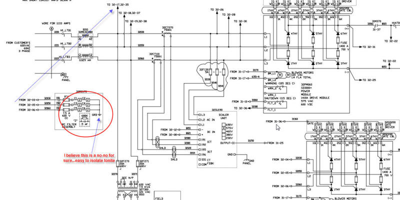
I have an RC filter across the three phase......R in parallel with C x 3 times on one side...all three connected to ground the other..
Connected to the same three phase I have an insulation meter.
I can confirm that when the three phase filter is isolated from the circuit, that the insulation meter is fine.
When the 3 phase filter unit is in circuit, it measures a low insulation.
Can this be due to the incorrect insulation meter being used? maybe the time for the caps to charge is too long and effecting the calculations in the insulation meter thus giving a false positive?
Any suggestions/ideas welcome!
S11S
 
Replies continue below

Recommended for you

Bender? Or what insulation monitor? A little bit more background could help.

Gunnar Englund
--------------------------------------
Half full - Half empty? I don't mind. It's what in it that counts.
 
Hi
it is a DRM 96-N
I understand that the system is actually ungrounded.....and they have grounded the noise filter.
I will check back up the line to the main transformer....see if it a star point secondary....and if starpoint is not connected.
If like this....I can remove this noise filter and the readings will be fine.
I have run for 3 days with no filter and it is fine; reading is good on the insulation meter and the crane is working fine.
 
I do not know that one - unless it is a standard square analogue meter.

Many insulation monitors use a low-frequency changing polarity DC test signal. If the capacitors in the filter do not charge fully in each half-period, you can get bad readings. Try to increase the length of the DC pulses and see if that helps.

Gunnar Englund
--------------------------------------
Half full - Half empty? I don't mind. It's what in it that counts.
 
Hi,
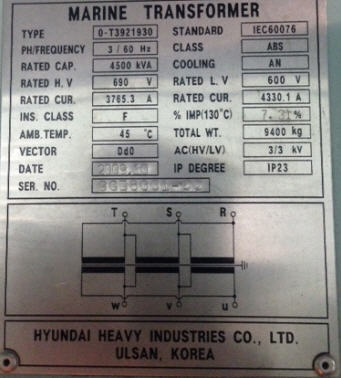
The transformer feeding this is a delta delta, primary/secondary.
I believe that is the issue - it is an IT ungrounded circuit...with this RC to ground causing an issue with the insulation meter being low.
 
Of course it is an IT Circuit (or II, I doubt that they exist IRL). Else you wouldn't have insulation supervision.

I tried to explain to you what may be the problem. And point to a possible way out. Did you understand what I said?

Gunnar Englund
--------------------------------------
Half full - Half empty? I don't mind. It's what in it that counts.
 
More info on this detection module so we know what it's doing would help.

However, if you have a monitor for an ungrounded system and you're using a filter which puts a resistor from each phase to ground then of course the monitor will detect those resistors as a ground fault.

I have an RC filter across the three phase......R in parallel with C x 3 times on one side...all three connected to ground the other..

 
I cannot imagine how such a filter would be constructed. RC filters in power systems are, at least in my world, series things. And if they are connected between the phases, I have extreme problems to see how they also can be connected to ground.

Please show us the circuit diagram.

Gunnar Englund
--------------------------------------
Half full - Half empty? I don't mind. It's what in it that counts.
 
They used to be called suppressors years ago.
A means of stopping radio interference.
When measuring insulation to earth/ground,you get a reading through the capacitive
element of the filter.
Disconnect the lead(s) connected to earth/ground while testing.


Hi,
Seen the three phase transformer secondary - clearly a delta winding - no fourth wire or ground.

crane_control_d2uguv.jpg


I have tried to attach the rc network drawing.
Basically three phase R in parallel with C...three times for each phase.
One side is connected to a lone phase of the 3 phase
the other side of the component are brought together and grounded.
Regards
S11S
 
That makes the whole thing a lot clearer!

Those resistors do not form an RC filter, they are discharge resistors and I do not think that you need them at all. There seems to be enough discharge paths in the equipment as such. So, if your code doesn't say explicitly that they are needed in an application like this, I would remove them.

But, of course, then the whole system's potential will stay at an undefined level when switched off, and that may be something forbidden in your Code. Helas, that is a property of all IT systems and if you can't have it - then you can't have a proper IT system.

Gunnar Englund
--------------------------------------
Half full - Half empty? I don't mind. It's what in it that counts.
 
Hi,
So the transformer feed is 45MVA....in the heart of the vessel.
To change it would be mind boggling in time, money - therefore it will not be changed - so they WILL be going with an IT system.
Removing this RC discharge network is very easy and basically no cost - and best of all for the CE, the low insulation reading will work for the first time ever!
S11S
 
THAT made me feel good! You get something for nothing. Doesn't happen every day.

Gunnar Englund
--------------------------------------
Half full - Half empty? I don't mind. It's what in it that counts.
 
Does the DRM 96-N use a zero sequence CT to infer current to ground and the reciprocal insulation value? If the instrument is connected to a CT that encircles all three main power conductors then passing the groundng conductor of the filter backwards through the filter may solve your issues.
However, the current through the three bleed resistors should cancel. If the resistors are 10% or 20% tolerance, it may be that one or more of the resistors is off the published value enough that the insulation montor is interpreting the uneven current through the uneven resistors as poor insulation integrity.
One of the resistors may be open.

Bill
--------------------
"Why not the best?"
Jimmy Carter
 
I don't see any transformer secondary....

Those look like capacitors with discharge resistors to filter higher frequency switching noise so it doesn't get into the power system. Gunner actually suggested removing the resistors, not disconnecting the filter ground and I agree with trying it without the parallel resistors first. I doubt the filter will be much use if you disconnect the ground point from ground and let it float. Depending on how the ground detection works, removing the resistors to ground could allow the filter to function without appearing to be an insulation failure to the detection unit.

 
What I can find out about the DRM 96-N insulation meter mentions CT connections.
Another option is three small transformers (2KVA) in a wye delta arrangement to provide a high resistance ground.

Bill
--------------------
"Why not the best?"
Jimmy Carter
 
I agree that the filter is direct connected without transformers, but I don't see the insulation monitor on that part of the drawing.

Bill
--------------------
"Why not the best?"
Jimmy Carter
 
Hi All,
There is no sign in any drawings of CT's for the DRM - I will be at site tomorrow and will physically/visually check.
The delta supply transformer is attached.
I like the idea of just removing the resistors and leaving the capacitors. I will try that.
tfx1_a6ellg.jpg
 
Hi,
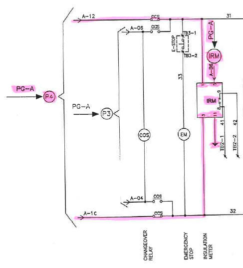
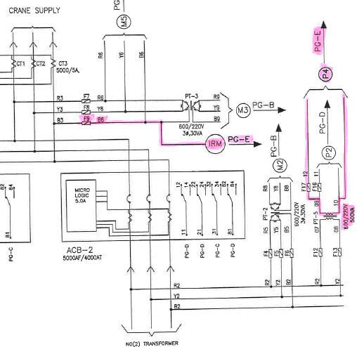
For insulation meter see attached.
This is pink line coming from the left comes from the delta transformer three phase supply...tapped off to feed a single phase transformer for this supply. There is no ground anywhere on this 600:230Vac control transformer.
in_meter_up8nzh.jpg
 
Status
Not open for further replies.

Part and Inventory Search

Sponsor