Eng-Tips is the largest engineering community on the Internet

Intelligent Work Forums for Engineering Professionals

RC hanging beam reinforcement at beam-beam connection 3

Status
Not open for further replies.

mr.rob

Structural
Jul 17, 2024
8
0
0
CA
HI all,
Long time reader, first time poster here. [glasses]
I have a beam-to-beam connection with large shear forces. This is in Canada to A23.3. Hanging stirrups in the girder are too closely spaced to fit in the 'hanging zone' because only 2 legs out of 6 would be effective.
My proposal is to add inclined bars to carry the shear force "up" into the girder so that all 6 legs of stirrups are effective. Any and all feedback would be greatly appreciated.

Capture1_avnx4v.jpg

Capture2_dcewvx.jpg
 
Replies continue below

Recommended for you

BAretired said:
When a beam is supported by a column, we don't worry about beam shear inside the column area.

I don't feel that is a valid comparison here. When a beam rests on a column, there is no need to consider a chunk of the beam ripping out in shear breakout as is the case when a beam is supported by another beam.

BAretired said:
I consider large bent bars in the carrying beam, not as shear reinforcement, but as a trapeze designed to transfer the reaction from bottom to top of the carrying beam.

That's just semantics. The "trapeze" that OP is proposing are being employed to address shear capacity. And they do so by grabbing the shear compression struts low and delivering that load back into the system up high, just like regular beam stirrups do. In fact, one might view these trapezes as simply inclined stirrups.

BAretirred said:
A23.3 requires us to carry the full reaction with steel, i.e. Vc = 0.

Which clause(s) of A23.3 deal with trapezes like this? I was not aware that there were any.

BAretired said:
It could be done with large vertical bars, but they would need to be anchored top and bottom to develop the full reaction of the carried beam.

Yes. But, then, the trapeze things also need to be anchored top and bottom. That's what informed my earlier comment:

KootK said:
It's always been a setup that suggests strut and tie checking but never seems to actually get it.
 
KootK said:
Which clause(s) of A23.3 deal with trapezes like this? I was not aware that there were any.

The first sentence in the one I quoted above, namely A23.3 clause 11.2.12.2.

KootK said:
Yes. But, then, the trapeze things also need to be anchored top and bottom. That's what informed my earlier comment:
Indeed they do have to be anchored top and bottom.

Whether large diameter bent bars, large diameter vertical bars or normal stirrups are used, they all have to be anchored to carry the full reaction of the supported beam. Avoiding congestion of steel is the goal.
 
Great article bones, thank you!
OP, I do not think I understand you fully. In the post where you replied to me you drew a red line where the crack forms - how does adding a diagonal bar change that crack? If it does not change it, then the leftmost vertical will never be able to cross that crack and it will never activate. This was the original idea, right?
IMO all the deiagonal does is that it adds more steel area that resists shear and this will help with congestion.
As KootK said, it's a weird strut and tie when you start to mix it (I don't know how to form it really), but I think that it would be safe to say that the mechanism does not really change and just add the projection of the diagonal steel area to the vertical steel. This would retain the same shear truss, but the tension vertical would be "larger".
 
@bones206: thanks for the article. That's new to me and and a useful addition to my library.

hardbutmild said:
In the post where you replied to me you drew a red line where the crack forms - how does adding a diagonal bar change that crack?

It doesn't prevent the crack. Rather, it drags some portion of the shear load up above, and over to the left of that crack. Just as a conventional beam stirrup does. This creates a new critical crack which then, hopefully, would see the associated compression strut engaging the stirrups farther into the interior of the beam.

To clarify my own position, I don't question whether the trapeze things work. What I'm unclear of is how to quantify their benefit rigorously in the context of modern design provisions which include strut and tie etc.

Inclined shear reinforcement, trapeze reinforcement, and moustache reinforcement are all permutations of a well thought out concept developed by our forebears. It's a very common setup in older bridge bents. I wonder if AASHTO might include an established design method for dealing with this arrangement.

c01_hcycle.jpg
 
BAretired said:
Indeed they do have to be anchored top and bottom.

That, then, becomes the crux of my concern. How does one ensure proper anchorage of a trapeze in your opinion?

I don't know but have the following thoughts:

1) For #5 or smaller, I'd provide a standard hook and not worry about it. This, based on the precedent set by our practice with normal beam stirrups. Granted, these are probably not small diameter bars.

2) Do a full on strut and tie design including curved bar node stresses at the bends etc. I see no one do this ever. And I suspect that there are parts of the model that would be incomplete and/or would not check out.

3) Develop the bars on either side of the presumed shear crack by utilizing the portions of the bars beyond the bends as well as the straight bits. Note that this is a method that is code sanctioned in some countries but, to my knowledge not in the US or Canada. And where it is sanctioned, I believe that it requires some attention to the bend radius to prevent concrete crushing.

The approach taken will have important implications for the detailing and placement of the trapeze bars. It may also make them somewhat sensitive to field placement issues.

c01_idjaym.jpg
 
KootK said:
That, then, becomes the crux of my concern. How does one ensure proper anchorage of a trapeze in your opinion?

Some form of mechanical anchorage may be required at the bend points. A substantial cross bar would help, but perhaps there are cases where more bearing area is needed. Conservatively, the anchorage should develop full yield in the cranked bar.

Cranked bars have been used in beams for many years. I don't believe anyone, myself included, worried about bearing stress at the crank point. To my knowledge, it has never proven to be a problem, but I could be wrong.

 
Not too concerned with the cranked bar bearing stress as others have said.
I would possibly hook the bar ends on the supporting beam up into the section for some extra "suspenders".

Screenshot_2024-07-22_175928_j9ee3l.png
 
KootK said:
It doesn't prevent the crack. Rather, it drags some portion of the shear load up above, and over to the left of that crack. Just as a conventional beam stirrup does. This creates a new critical crack which then, hopefully, would see the associated compression strut engaging the stirrups farther into the interior of the beam.
I agree. I was under the impression that OP meant something different and I wanted to clarify this.
Regarding your concern 3): it should not be that hard to make a larger bend of the bar... with the bend radius of 15D #8 bars spaced laterally at 4" in 4000 psi concrete should be able to develop roughly 60 ksi (based on Eurocode). Adding a transverse bar (as OP has in his drawings) should also help significantly.
I guess you don't really need to develop 60 ksi at the bend since most of the force is already anchored.
WestLevel said:
I would possibly hook the bar ends on the supporting beam up into the section for some extra "suspenders".
I don't like this, why not just make a longer bar?
 
What is needed is a hanger assembly capable of carrying the factored reaction of the supported beam. The most direct method is a group of vertical tension bars in the overlap area of the carried and carrying beams. They must be mechanically anchored top and bottom; and they should be confined by horizontal ties crossing the potential crack.
 
I appreciate everyone's responses and interest in the subject!

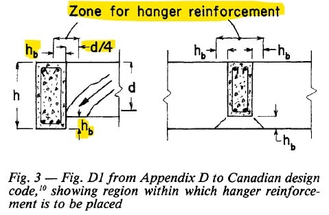
bones206, thank you for the reference document. Very informative. Also noting that earlier version of this requirement extended the 'zone of hanger reinforcement' by as much as d/4 into the supported beam for beams of equal depth...something that the current revision does not.
Screenshot_2024-07-23_145811_esb80e.jpg


KootK, to address your comment about lack of a 'robust mechanism for checking', I agree that this is, in general, an incomplete truss-and-tie set-up that doesn't carry the load to any definitive end. This being said:
1. Both the supporting and the supported beams have all the required one-way shear and torsional reinforcement stipulated elsewhere in the design guide up to and through the intersection.
2. The diagonal bars are in addition to all other transverse reinforcement and are required to address the discrete issue of the concrete breakout in a hanging beam scenario where rebar congestion is an issue.
3. Given 1&2, if the concrete breakout failure may be addressed by the additional diagonal bars, then all other reinforcement will still be there to ensure that other modes of failure do not occur. For this reason, in my opinion, a truss-type 3D model that aims to replicate all developing struts and ties may be avoided once the diagonal bars are extended/developed outside of the 'zone of interest', and if all stirrups in the supporting beams are engaged.

Regarding forces, placement, etc.
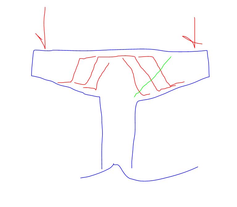
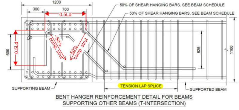
- Compression strut check as per strut-and-tie model. yes. This is one of the reason why two offsetting rows of bent bars are proposed.
- The bars to carry full shear across the interface at an angle of 45 degrees. Rebar force = 1.414xVf.
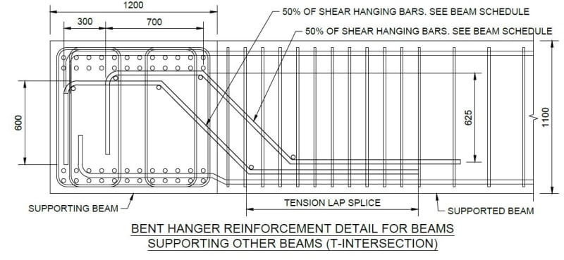
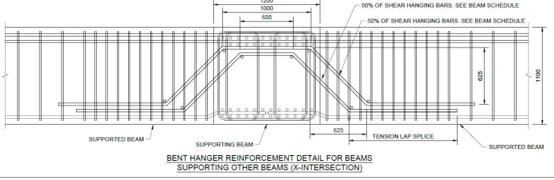
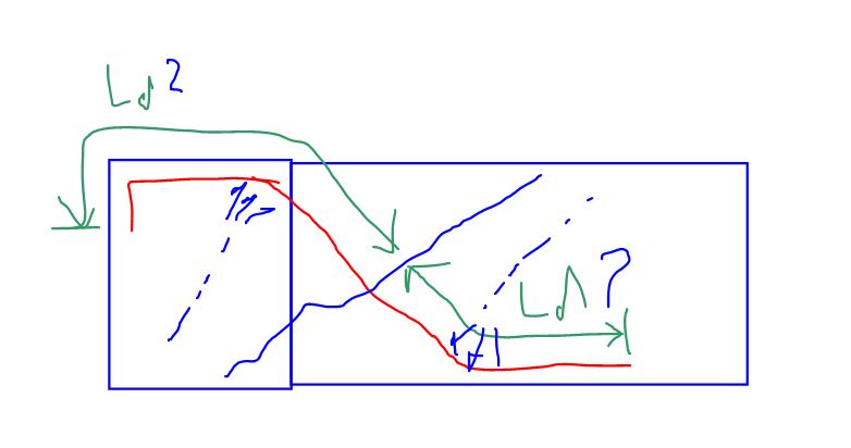
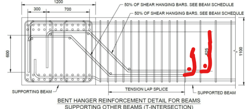
- For the T-intersection case, arguably the more difficult of the two being discussed, the bars are fully developed before the first bend in the supported beam. Tension splice is what I actually called out.
- For the end of the bar in the in the supporting beam, I consider that ~ 50% is developed before the first (90deg) bend and fully developed before the next (45deg) bend. This way I rationalized approximately equal forces between the 2 forming struts in the supporting beam.
- The force from the diagonal bar should create torsion in the supporting beam. This torsion being no different to the force caused by eccentricity of compression strut in A23.3 CL 11.2.12.2 about center of the supporting beam. Transverse reinforcement to resist this force should already be there as prescribed by other clauses of the design guide.
Capture1_avnx4v_e6hiwx.jpg


Some testing and prescriptive guidelines would certainly instill more confidence...as for anything else I suppose.
 
Status
Not open for further replies.
Back
Top