Continue to Site

Eng-Tips is the largest engineering community on the Internet

Intelligent Work Forums for Engineering Professionals

  • Congratulations KootK on being selected by the Eng-Tips community for having the most helpful posts in the forums last week. Way to Go!

RCC INDUCTA 2

Status
Not open for further replies.

N.K.

Structural
May 30, 2019
14
Hi all,

Has anyone used INDUCTA RCC for column design recently (with the AS3600:2018 code incorporated)? I have currently run a few column designs using it and noticed that the decompression point calculation is wrong. Now I just want to confirm if it is actually wrong or if I am missing something. I have compared it to a hand calculation that I performed and to the calculation performed by structural toolkit both cases the results did not match. I would like to know if i should abandon the application.

Thanks!
 
Replies continue below

Recommended for you

If you want some assistance give us at least a page of your hand calculations and a page of the programs output to have some idea of what you are seeing.

Otherwise anybody who wants to assist you is just guessing what you are doing.

Jim

 
our office uses RCC, and i havent heard anyone raise the decompression comment, will raise it on monday. i have found that Inducta's support has been pretty responsive, have you raised it with them?
 
I will say a few things that may or may not be helpful. I am sure you will be aware of a few of these.

First of all be mindful of capacity reduction factors - these come into play and sometimes they can be a manual input that is set to some default value. Make sure that the capacity reduction factors are consistent across all your comparisons.

Secondly be mindful of the underlying assumptions. Multi-reinforced section calculations can get fairly involved and so bear in mind that your underlying assumptions can vary to those made by the software providers. Having said this your result should still be qualitatively the same as the software output (provided that your calculation is correct). Make sure that you use the correct compression block.

Thirdly - assuming that you work at an Aussie firm I assume that you have access to RAPT. RAPT can do column interaction diagrams and so it can be useful as an additional cross-check.

If the above is not enough give me a test concrete section and I can act as another source of a cross-check. I have a small script that outputs factored and unfactored interaction diagrams.


I've checked the load factors they are all the same. For a 1000x200 (5N16s top and bot) It seems the difference is coming from assumptions each program is making. RCC is assuming a Ku(dn/ds) = 1 while structural toolkit and rapt assume a Ku = 1.379 (dn/ds = 200/145). This is 35mm cover and N12 ties.
I assume RCC is taking ku as 1 to ignore the cover concrete and make the extreme fibre, with 0 strain, at the steel level. This ends up giving less axial capacity but an increase moment capacity.
Conversely, with a ku=1.379, we get an increased axial capacity but a decreased moment capacity.

Which of these two do you guys assume is the most realistic assumption?
 
Just curious, what is the "decompression point". is it related to unloading, or the points on the curve after balanced point?
 
The Decompression Point is a problem with the rectangular stress block used to determine the concrete forces, and the problem becomes worse as concrete strength increases, especially about 50MPa. This can be easily verified for cases where gamma = .67. With gamma = .67, the centroid of compression force is at .333d which is the centroid of a triangle of depth d. The actual concrete stress/strain is not a triangle so this is seriously underestimating the depth to C and therefore the calculations for the decompression point.

RAPT uses a stress block based on the Eurocode parabolic-rectangular block which gives a much better estimate of the centroid of the concrete compression force in sections that are fully in compression.

The rectangular stress block is not too bad for pure bending but becomes less and less accurate as the axial force component increases!

I have no idea what you mean by "RAPT assume a Ku = 1.379 (dn/ds = 200/145)". RAPT does not assume anything.
 
Hi Rapt,
Sorry when I said it assumes I meant to just state the the ratio depth to neutral axis is reported as 1.379 in RAPT when I did the analysis.

That still does not explain the different result that RCC is getting. It seems the extreme fibre where strain is equal to 0 is taken at the centroid of the steel as opposed to the full depth of the concrete. Is this a correct a assumption to determine the ERSB.

How does this affect the interaction curve? Does it give a more conservative result? It seems the moment capacity increases whiles the axial capacity decreases.


For a rectangular cross-section, it is a simple calculation to find a stress reduction factor and depth factor for a rectangular stress block that will give precisely the same force and centroid depth as a parabolic-linear stress block, with any strain limits and any exponent on the "parabolic" part, for any depth of neutral axis within the concrete section.

Why not one code in the World (as far as I know) actually does this is a mystery to me.

That doesn't apply for non-rectangular sections, where it makes more sense to forget the simplifications and just do the maths.

Doug Jenkins
Interactive Design Services
 
IDS,

I agree entirely. As you know I have been pointing this problem out to the powers that be for a long time. I was told that the adjustments made in 2018 were supposed to fix this. I will say no more! The Canadians also told the AS3600 committee their factors were wrong many years ago, a few years after I raised it. They think theirs are correct, but I think you will find the same problem for the lower limit on the factors for higher strength concretes.

N.K.
I have no idea what Inducta does. It should be 0 strain at the extreme concrete surface that is normally tensile, not the level of the steel.

The centroid problem makes a big difference. Normally it will be in the order of .4d instead of .33d and that might no look like much, but when you transform it to distance from the plastic centroid, it is .167d instead of .1d, and most of the Moment in Mu at decompression is from the concrete compression force so C * that number as all of the tension face steel is in compression and near 0. So that component of Mu is wrong by about 40%!
 
From rapt description, it seems you are concerned with the assumption/calculation of compression block. I think you are using EU method, which I don't have any idea on the equations and parameters, but a quick search I found the definition of Ku (neutral axis depth parameter) = dn/d, which will always be less than 1. From this finding, I suspect you may have made mistake on your calculation. Can you show us your calculation, along with equations, and a sketch of you concerns.
 
What is RCC Inducta? Is it the organisation that has all the old RCC spreadsheets, currently updated? I copied all the RCC sheets that were available back about a decade or two; are these the same sheets, but updated to current codes?

Dik
 
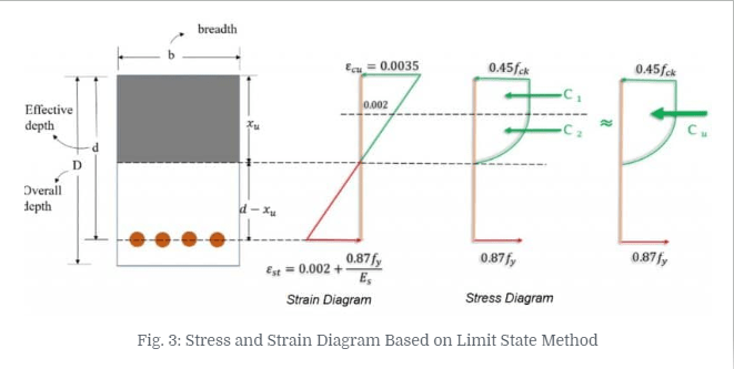
Maybe this will help us stay on the same page/terminology. I think dn is Xu in the sketch below.

image_q4gmec.png
 
Dik,

Inducta is an Australian company that puts out some analysis and design software. I assume RCC Inducta is their RC Column program. Not sure as I never look at opposition products.
 
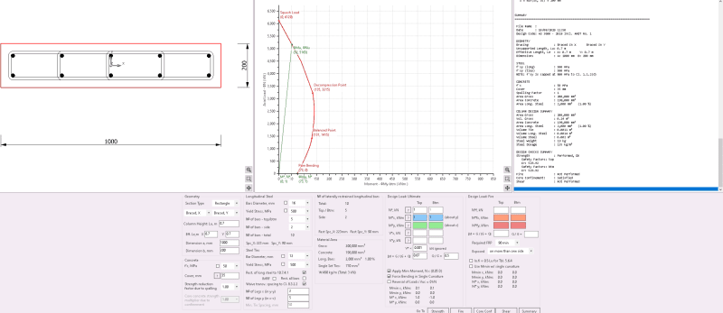
So apparently RCC Inducta use a parabolic stress profile but take the point of zero strain at the tensile steel depth.
I have attached my hand calcs that shows results when the 0 strain is at the face of the concrete.

I have attached the RCC output for clarification.

RCC_PLOT_hansea.png


Do you guys think that despite this difference the interaction curve should still be the same as the case of 0 strain at the tensile steel level is a point on the curve.

Thanks.
 
In your hand calc, I don't think you are accounting for the fact that the bar stresses need to account for the fact that the bars are displacing the concrete. So the net stress should be used for determining the moment on the assumption of the full concrete area being used without deducting the holes for the concrete where those bars are within the rectangular compression block depth (dn*gamma). i.e. using net bar stresses, it is (n-1) times your gross bar stresses you worked out. Where n is the modular ratio (Es/Ec).

 
Yes I didn't account for the steel area but that shouldn't result in the difference between the two calcs. The difference would be small compared to what is shown between RCC and the hand calcs.
 
Maybe try posting a better image of your rcc output as it's virtually unreadable to me to compare anything. Too blurry.
 
Looks like far better minds have been contributing to this thread with some actual technical advice (as opposed to my platitudes).

@N.K - your hand calculation looks OK; it's no worse than any capacity check that I carry out in my spreadsheet and it comes up with exactly the same values. I think you need to take a look at what people have posted here and decide what type of compression block assumption you want to go with. My two cents is that a lot of people usually have differing opinions but at the end of the day you are the design engineer and you have to make decisions. My position in these situations is that as long as you stay within the boundaries set out by the relevant standard your design will be safe (in the aggregate). It is quite rare for the design codes to be non-conservatively wrong and whilst healthy skepticism is always...healthy, you simply cannot spend your life second-guessing design guidance that quite intelligent academics take years to compile.

P.S. - that's a funny-looking column you have there. N12 ties too are looking suspiciously like horizontal wall reinforcement placed in the outside layer. Are you by any chance trying to design a wall using AS3600-2018 Section 10 framework? I only ask because I am curious.
 
RCC is assuming a Ku(dn/ds) = 1
Are you sure about this? ku = dn/ds by definition.


With gamma = .67, the centroid of compression force is at .333d which is the centroid of a triangle of depth d. The actual concrete stress/strain is not a triangle
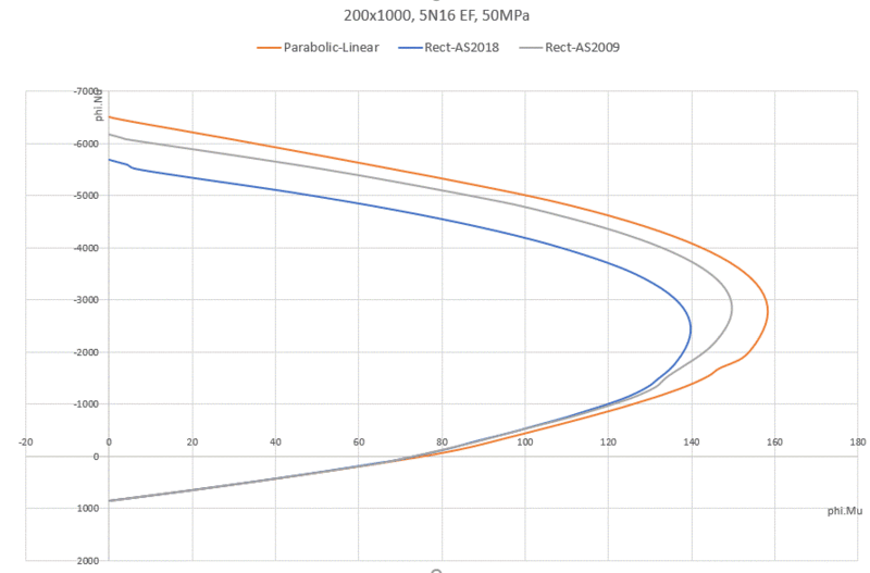
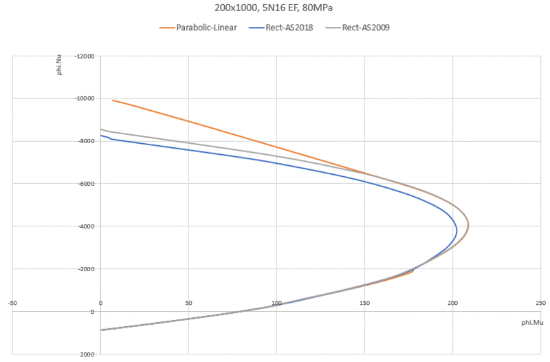
For high-strength concretes, the EC2 parabolic-linear stress block becomes quite close to a triangle in the part of the curve that's used. In the 80MPa graph below, the departure between the EC2 and the AS3600-2009 'triangular' result is mostly in the part of the interaction curve that isn't used due to minimum eccentricity. Bear in mind that EC2/parabolic-linear isn't perfect, so departure from it isn't necessarily wrong. The rectangular stress blocks are trying to (should try to) match reality, not some other simplification.

50MPa_column_oqocmt.gif


80MPa_column_k185d0.gif
 
Status
Not open for further replies.

Part and Inventory Search

Sponsor