Continue to Site

Eng-Tips is the largest engineering community on the Internet

Intelligent Work Forums for Engineering Professionals

  • Congratulations KootK on being selected by the Eng-Tips community for having the most helpful posts in the forums last week. Way to Go!

RCC INDUCTA 2

Status
Not open for further replies.

N.K.

Structural
May 30, 2019
14
Hi all,

Has anyone used INDUCTA RCC for column design recently (with the AS3600:2018 code incorporated)? I have currently run a few column designs using it and noticed that the decompression point calculation is wrong. Now I just want to confirm if it is actually wrong or if I am missing something. I have compared it to a hand calculation that I performed and to the calculation performed by structural toolkit both cases the results did not match. I would like to know if i should abandon the application.

Thanks!
 
Replies continue below

Recommended for you

My set of RCC spreadsheets described in the attached... date back about 10 years or so... There are about 40 programs. They are very detailed and very useful, albeit dated. I've used some of the constructions for other sheets that I have written.

Dik
 
 https://files.engineering.com/getfile.aspx?folder=7ba37122-2e24-48bf-bbe7-4fa467eca9d6&file=RCC_Documents.pdf
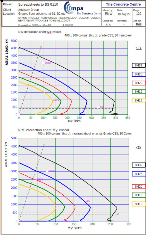
Typical part sheet from RCC Concrete Column:

Interaction_Diagram_ga41zx.png


Dik
 
Steveh,

Yes it is closer to a triangle for for high strength, over about 80MPa, but it is still about 20% above a straight line so assuming a straight line is unconservative in this calculation of the Compression Concrete effect. But he is using 50MPa.

N.K.

N.K. said:
So apparently RCC Inducta use a parabolic stress profile but take the point of zero strain at the tensile steel depth.

Are you sure about RCC using a parabolic stress/strain curve? I cannot see anything to indicate it

captain_slow

captain_slow said:
you simply cannot spend your life second-guessing design guidance that quite intelligent academics take years to compile

You obviously have not been involved in the process!
 
Rapt,

rapt said:
Are you sure about RCC using a parabolic stress/strain curve? I cannot see anything to indicate it

Yeah I emailed and asked and they also confirmed that the neutral axis is taken at the steel depth not the section depth.

Captain slow,

its just a test column. Don't know why I selected that to be honest.

Also the project has multiple column types with a range of concrete strengths.

All,

I think I kind of know where the problem is, If I am to plot the entire curve using the normal calcs from the code the curve essentially matches so its perhaps just a different interpretation as to where the decompression neutral axis should be taken. Although, I think it should be at the edge of the section not steel level, that's the logical position.
 
N.K. said:
I think I kind of know where the problem is, If I am to plot the entire curve using the normal calcs from the code the curve essentially matches so its perhaps just a different interpretation as to where the decompression neutral axis should be taken. Although, I think it should be at the edge of the section not steel level, that's the logical position.

I was about to say something similar. The effect of taking the NA at tension steel level is just to move the "decompression point" slightly to the right along the interaction curve. It means the straight line interpolation to the maximum axial load point is introduced a little earlier, but since the line is almost straight over that region anyway, it makes very little difference to the final load/moment capacities.

I will be making some detailed comments on the factors for the rectangular stress block a bit later, since these do make a significant difference.

N.K. It would be helpful if you could upload a readable image of your Inducta results.

Doug Jenkins
Interactive Design Services
 
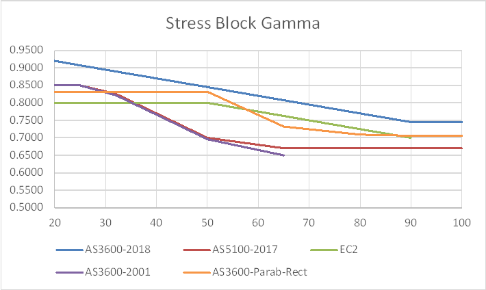
Let's have a look at Australian code and Eurocode factors on the depth of the rectangular stress block:
StressBlock1-1_s6xncz.png


The orange line (AS3600 Parab-Rect) is my calculation of the rectangular block depth that will have exactly the same centroid as the Eurocode parabolic-rectangular block. Comparing with the other lines:
- The Eurocode 2 rectangular stress block follows the same trend, but is significantly lower up to 50 MPa.
- The AS 3600 2001 and 2009 line (which eventually made it into AS 5100 in 2017) is very close to my line at 32 MPa, but much lower at 50 MPa, and significantly lower right through to 100 MPa.
- The new AS 3600 (2018) line is higher than my line over the full range, but comes close at 50 MPa.

So what effect does all that have?
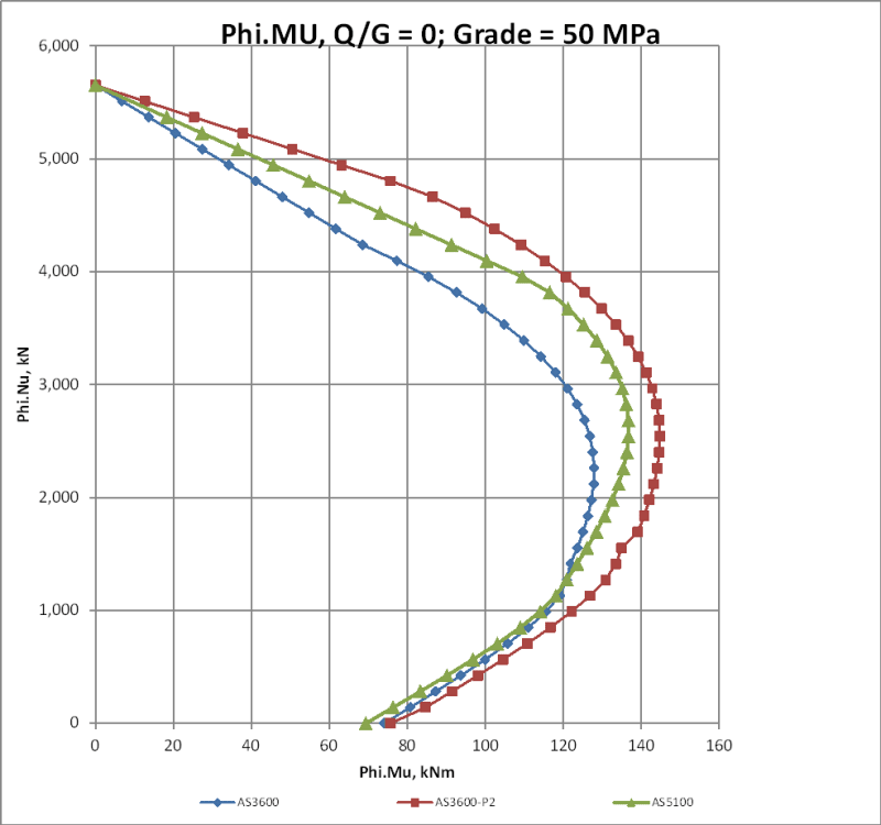
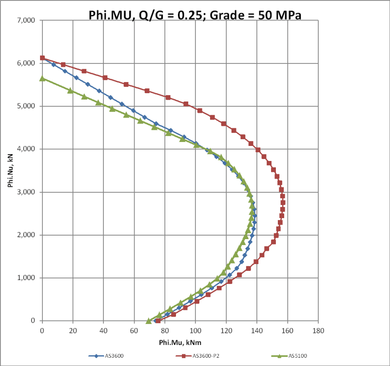
Comparing my line (red) with the new AS 3600 (blue) and latest AS 5100 (2009 AS 3600) (green)
For 50 MPa with equal reduction factors for a lines:
StressBlock1-2_oa6o7n.png


Increasing the Phi factors for the 2018 and my lines:
StressBlock1-3_rpq7sm.png


So in spite of the increased lever arm, the AS 5100 line gives a smaller bending moment than my line, although significantly more than the new code for mid to high axial loads. Using the higher phi factors in the new code, the new AS 3600 line is close to the old one over most of the range.

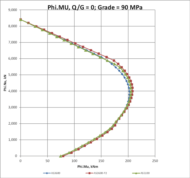
For 90 MPa concrete with equal phi factors:
StressBlock1-4_h4qx5c.png


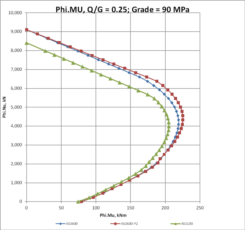
and increased phi for the latest lines:
StressBlock1-5_n3rmhb.png


With equal phi values, all three curves are very close over the full range, and with the increased phi values the new curves give significantly higher moment capacity, with my line being slightly higher than the code line.

So what's happening?

In order to produce the same response as a parabolic-rectangular stress block, as well as adjusting the depth of the block to match the lever arm, the stress factor (alpha) should be adjusted to generate the same force. The graph below shows that the force generated by the current AS 3600 curve is significantly less than my line based on the Parabolic curve, and the 2009/AS 5100 line is lower still:
StressBlock1-8_hbbegq.png


Doug Jenkins
Interactive Design Services
 
IDS, what is the Q/G ratio in the titles in this context? (not overly familiar with AS3600)

Are you comparing the same section as the OP?

 
Agent666,

I thought you shared the same Loading Code. G = DL and Q = LL.

I assume the difference is because some idiot introduced a variable phi factor into AS3600-2018 dependent on ratio of Q/G.
 
Ah, yes that will be why it went over my head....

We have a constant phi here in NZ of 0.85 no matter what, life is simple, our structures for the most part stand up just as well as yours always have.

Didn't/can't even comprehend using a variable phi based on load ratio? That sure as hell makes things hard for the poor designer, different capacity/interaction curves for every load combination.... sounds like some researcher went mad and threw out any semblance of practical design and efficiency occurring out in industry. Perhaps for the sake of a few more kNm, but is it even worth it if you are adding more opportunities/chances of someone getting it wrong?

Curious if most people just practically design for the most conservative ratio out of all their load combinations to make it easier, or actually look at different individual cases for each and every load combination and member?

Curious what logic there is behind saying a column with live load + dead load has less capacity than the same column with just dead load. I would have naively thought load is load. What physical mechanism is at play here? Or is it just a code fudge to more closely match observed test results or something?

 
Agent666 - Yes, it's the same section as in the OP. I'm not sure why I'm getting different results to steveh49.

Maybe a fixed reduction factor makes sense when a high level of confinement is standard practice (or is supposed to be standard practice), but for Australian code requirements for confinement a lower phi where compression controls makes sense (and is also applied in US codes, and in effect in Eurocode 2). A lower phi for permanent loads with a low load factor, compared with occasional short term loads with a much higher load factor, also makes sense to me, although it could be argued that the Australian codes are already conservative compared with other World codes, without the low phi value. But in practice when using a computer to check the reinforcement requirements, it makes very little difference to the amount of work required anyway.

rapt - The main point of the graphs was that even at 50 MPa the AS 5100/old 3600 line was conservative compared with the parabolic-rectangular stress block over the full range, even without the change in phi, and the new gamma factors have increased that conservatism.

So there is now yet more reason to use the parabolic-rectangular block, especially since for a rectangular section there is a closed form solution that is just as simple as using the rectangular block.


Doug Jenkins
Interactive Design Services
 
Cheers IDS, yeah I guess NZ have more onerous confinement criteria compared to some international codes due in part due to our seismic requirements. It's always been that way, it's one of those things that's normal to me, but others used to less onerous conditions internationally will probably think they border on overkill.
 
Agent666,

Couldn't agree more about variable Phi values, but that was another argument I lost several times(I seem to lose a lot when dealing with Academics!!).

It was shown apparently that for Q/G of between about 0.1 and .2, the statistical possibility of failure was nominally above the nominated limit. So basically when you have just about no LL! Our Phi for flexure for columns used to be .85 also, now it is .9 except for the case above!

Common sense did not prevail again.

IDS,

Agreed for the overall curve, But the Decompression is a long way from where it should be, so if there is a calculation that is dependent on the Decompression Point values, it is way out!
 
Doug, no doubt a few shortcuts on my part will contribute to differences. Eg I use the bending rectangular block all the way up to squash load instead of the squash load parameter given in clause 10.6.2.2. I also use 0.9*f'c in the case of the parabolic-linear calculation (clause 3.1.4) and ignore the spalling of the cover concrete. That's why my squash loads are all different whereas yours all meet at the same load. I don't usually have columns in that part of the curve anyway so can live with it.

My curves used the 0.65 phi factor.
 
steveh49 said:
My curves used the 0.65 phi factor.

I think that's the main difference, in the region of the balance load anyway. I used 0.6 for the AS5100 line in all cases (because it is still using all the same factors as AS 3600-2009).

Doug Jenkins
Interactive Design Services
 
rapt said:
It was shown apparently that for Q/G of between about 0.1 and .2, the statistical possibility of failure was nominally above the nominated limit. So basically when you have just about no LL! Our Phi for flexure for columns used to be .85 also, now it is .9 except for the case above!

I think you must have had a different code in mind when you wrote that. The new AS 3600 increases the phi for pure bending from 0.8 to 0.85, and it is applicable to all Q/G ratios where normal ductility steel is used (remains at 0.8 for low ductility steel).

I have posted modified versions of my graphs above at:

It also has links to a short VBA function to calculate rectangular stress block parameters that are exactly equivalent to the Eurocode 2 parabolic-rectangular stress block (for a rectangular section), and a conference paper I presented in 2011:

My conclusion back then was that for a rectangular section the code rectangular stress block was close enough for all practical purposes. With the revisions in the latest version of AS 3600 I now think it makes sense to use the parabolic equivalent block for rectangular sections, and use the full EC2 parabolic-rectangular block for non-rectangular sections.


Doug Jenkins
Interactive Design Services
 
IDS,

Must have been early in the morning and I got mixed up between my .6's and .8's.

We are talking about column interaction diagrams.

For Combined bending and compression, Table 2.2.2(d), it is .65 except when Q/G < .25 when it is .6.
 
Hi N.K - it's a late post but I thought I might be able to help others with this question.

TL:DR: when validating an axial moment interaction diagram don’t use the decompression point. It’s an imprecise term as defined by AS3600:2018. Instead compare the results to the same neutral depth axis. All calculations to generate a moment-interaction diagram as calculated w.r.t the neutral depth axis. With this calculation you’ll be able to tease out the difference more easily.

The term “Decompression Point” can be a little bit misleading because of the discrepancy you point out. In the Australian Code the decompression is not well defined but the “extreme tensile fibre” refers to the concrete extreme tensile fibre. That is, the decompression point referred to the point on the axial-moment interaction diagram of the stress block spanning from edge to edge.

I think the confusion is due to context. Concrete is assumed to provide no tensile strength in column design so talking about the “concrete extreme tensile fibre” might seem incorrect. Occasionally the steel is assumed to take the tensile force and occasionally then is assumed to be the “extreme tensile fibre” as stated in clause 10.6.2.3 of AS3600.

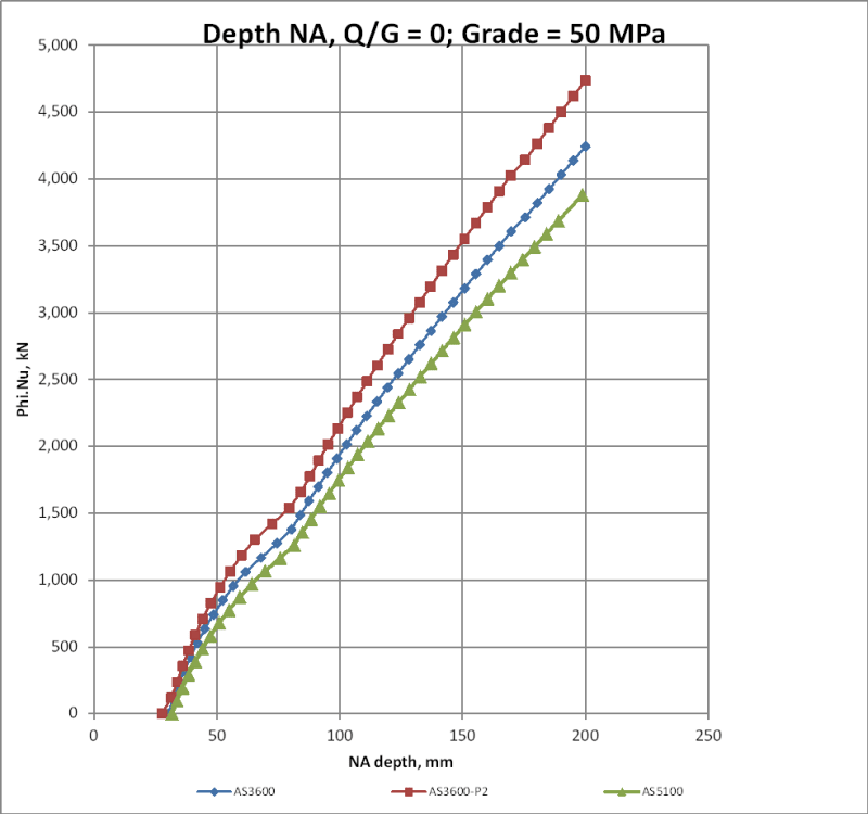
Truth be told the exact placement of the “Decompression Point” doesn’t actually matter. When validating an axial moment interaction diagram the only thing that matters is the position of the neutral depth axis. So instead of trying to compare decompression points across different programs use the neutral depth axis. Each point on the axial-moment diagram is generated from a given neutral depth axis position on the cross section.


Complete Columns
 
Status
Not open for further replies.

Part and Inventory Search

Sponsor