Continue to Site

Eng-Tips is the largest engineering community on the Internet

Intelligent Work Forums for Engineering Professionals

  • Congratulations GregLocock on being selected by the Eng-Tips community for having the most helpful posts in the forums last week. Way to Go!

RCP Through an Existing Concrete Seawall 1

Status
Not open for further replies.

supstr

Structural
Jun 15, 2016
9
I'm working on the details for making an opening in an existing concrete seawall through which a 48" RCP will pass through at one location and a 72" RCP will pass through at another location. The seawall is located in a canal. No drawings or information is available for the seawall other than what will be ascertained from a visual field review.

I'm going over a few options on how to address this situation:
1) Saw cut a rectangular hole 3"-6" larger, on all sides, than the O.D. of the RCP in the seawall. Drill and epoxy in rebar to essentially provide an opening reinforcement detail around the pipe. Fill the interstitial space with concrete/grout.
2) Frame a rectangular opening 3"-6" larger, on all sides, than the O.D. of the RCP with stainless steel channels (or other shape). Saw cut hole, fit RCP, and fill interstitial space with concrete/grout. The steel members would stiffen the opening and transfer the load. This detail would be carried out on the canal side of the wall.

My questions:
1) Has anyone designed for a similar situation in the past and can provide any advice or insight?
2) Any additional options that could be considered?
3) Any pitfalls to avoid?
4) For option 2, would embedding the members in soil be advised?


Any advice or questions for clarification are welcome.

Thanks.
 
Replies continue below

Recommended for you

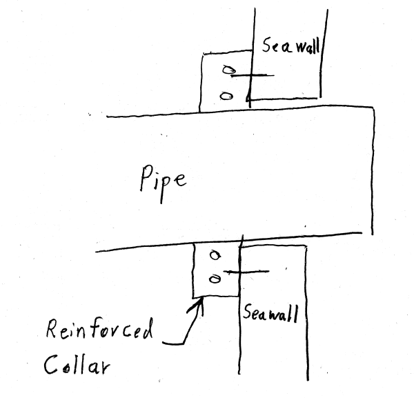
Consider sawing the hole per your Option 1.
Install the pipe and grout it in place (no rebar or dowels at this time).
Then drill and install dowels in the face of the wall (either side).
Form and place a reinforced concrete collar that encases the pipe.

You want to keep each step as simple as possible when working under adverse conditions (below ground level) and in tight spaces. See the sketch below:

Pipe_Opening_i1xliq.png


[idea]
[r2d2]
 
SlideRuleEra,

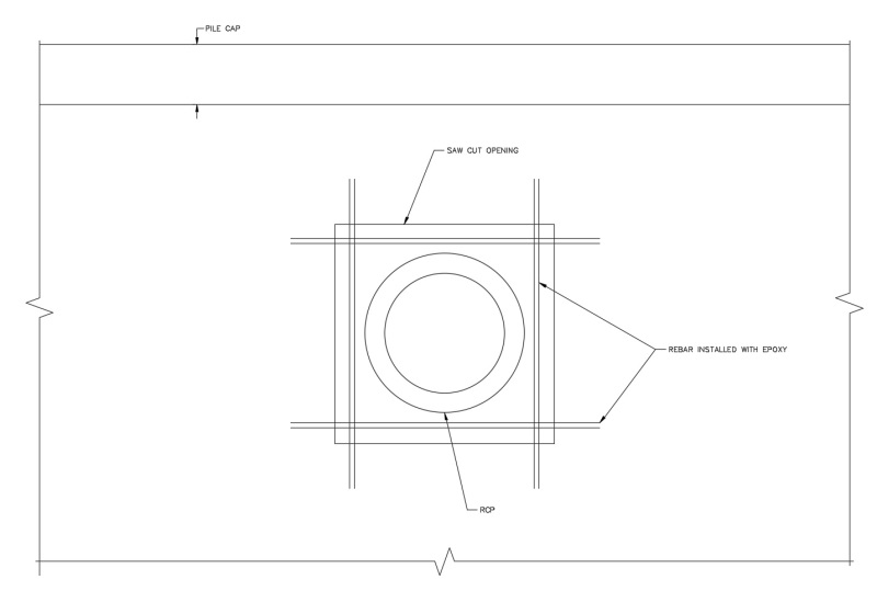
Would this detail transfer the flexural load in the wall to the ends of the wall? Perhaps, I misled with the wording of my post, see sketch below of an elevation view of option 1:
ELEVATION_SKETCH_fpwmbi.jpg


I think a collar would be a good option for restraining axial load in the pipe. In this case, the pipe is not pressurized and will not have any axial load. I'm concerned with ensuring that the load path that is being interrupted in the wall with the large hole can be redirected via a detail of some sort.
 
supstr - What are the details of the seawall?
Is it driven concrete sheet piling? How thick? Any tiebacks or just a cantilever wall?
Since the pipes are large will any sheets be cut completely (the horizontal saw cuts)?
Is there fill on one side? How high?
Any load applied to the pile cap?
What elevation is the water table, compared to the pipes?

Sorry for the number of questions, but as usual the details will probably make the difference in what is practical and what is not.

[idea]
[r2d2]
 

SlideRuleEra,

No problem, I appreciate your replies and your questions will help me prepare for the site visit.

I have many of the same questions that you have and I will have to get some more information to update the thread with early next week. I wanted to prepare a bit in advance of the visit as I haven't designed a detail for this particular application.

Responses to your questions below:
Is it driven concrete sheet piling? How thick? Any tiebacks or just a cantilever wall? This is information that I'm trying to determine during my field visit next week. I'd imagine that the wall is a driven concrete sheet pile given the history of construction techniques in this area. I would not expect a retaining wall with a heel, toe, etc. I will try to find any signs of the wall being tied back. I would expect the tie backs to be relatively close to the surface (the pile cap is about 8-10" high). Do you know if it is unreasonable to expect to see the tie backs without excavating extensively?
Since the pipes are large will any sheets be cut completely (the horizontal saw cuts)? This is a concern I raised with the site civil eng. and will investigate with field measurements and drawings that will be prepared by the site civil eng. early next week.
Is there fill on one side? How high? There is fill on one side that goes up to the top of the pile cap.
Any load applied to the pile cap? If the wall is tied back, then there will be a load. If the cap is found to not be tied back, then I don't expect there to be very much load (primarily shear) as the cap will move with the wall.
What elevation is the water table, compared to the pipes? I will provide the thread with an update next week.
 
Do you know if it is unreasonable to expect to see the tie backs without excavating extensively?
I would expect the tiebacks to be fairly high on the exposed wall, maybe even in the pile cap. They may be visible on the canal side. If you see them, be sure to get the horizontal spacing in addition to the elevation.

See if there may be a surcharge load on the wall, say buildings set back just a short distance from it. Even maybe a street or sidewalk parallel to the wall.

If it applies, find out if the canal water is fresh, brackish, or salt. Also if the water is tidal and the typical tidal range (Low Tide to High Tide).

Be sure to take good photos, some from a boat or dock, if possible. I'd like to see what you have. [smile]

[idea]
[r2d2]
 
SlideRuleEra,

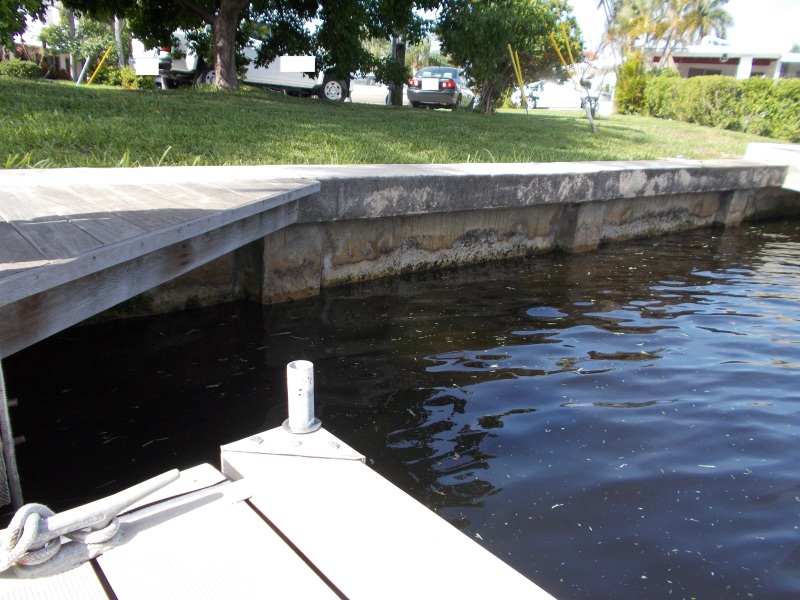
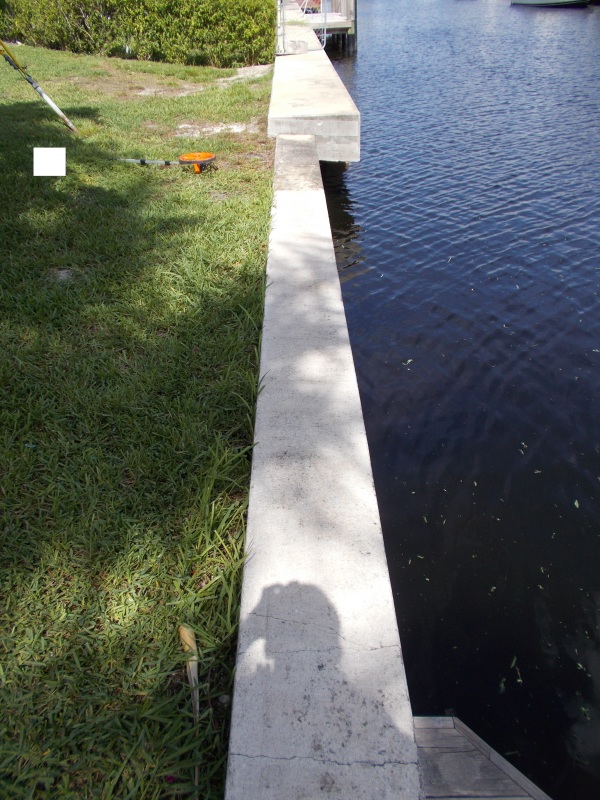
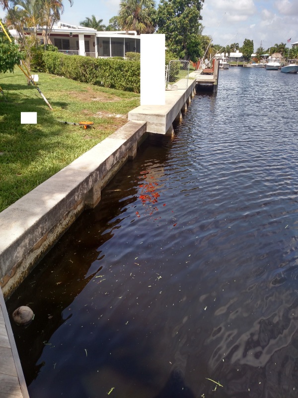
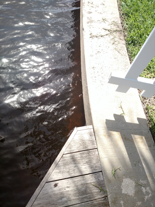
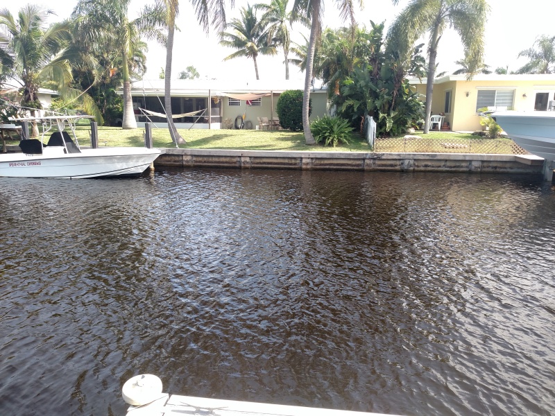
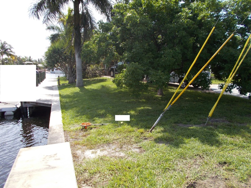
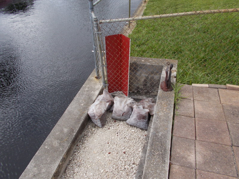
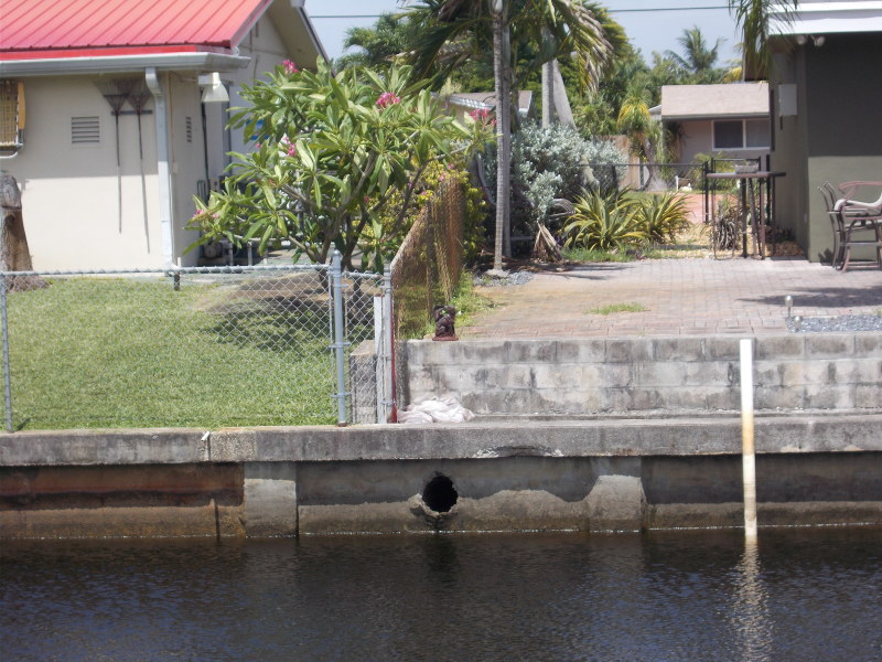
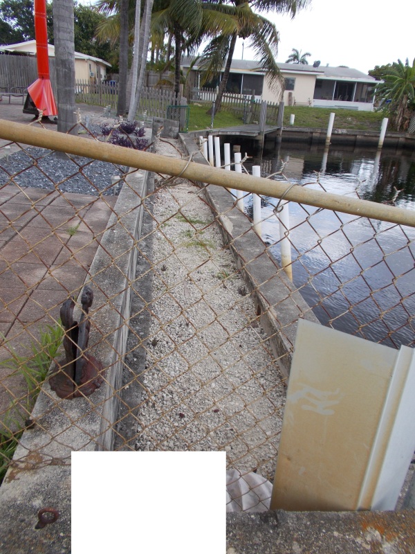
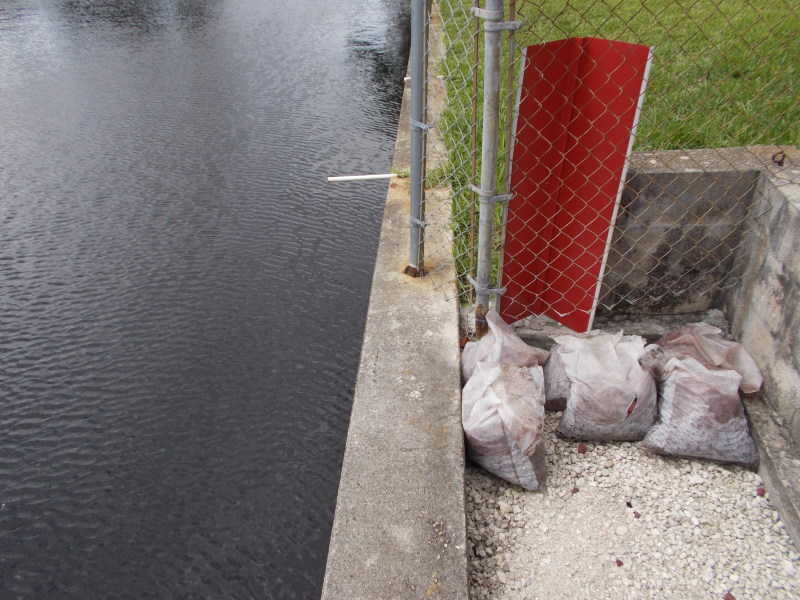
I got out to the field to see each of the walls. I have attached a few photos for reference.

Here are some of my observations:
[ul]
[li]The walls are not driven concrete sheet piling as I expected, they seem to be cantilever retaining walls - I could see the front portion of the base slab. [/li]
[li]The wall does not seem to be tied back. The pile cap is about 9"Hx16" and 9"Hx13.5". From the dock where I was able to see the wall from, I did not see any evidence indicating that wall is tied back. I also did not see any indication of tie backs in the pile cap on the land side.[/li]
[li]I measured the distance to the top of the base slab of the wall at each site. At one site (Site A), where a 72" RCP is being proposed, the wall is 4'-4" tall - measured from the top of the cap to the top of the base slab. At Site B, where a 48" RCP is being proposed, the wall is 6' tall. There is survey information for the canal at Site B but, not at Site A (I expect to get some more survey information in the next few days.)[/li]
[li]There was some cracking in the pile cap at Site A, although they appeared to be shrinkage cracks not shear or flexural cracks. At Site B, there were some rather large cracks in the cap which, can be attributed to poor work performed by the homeowner or a contractor to install irrigation drainage lines. There was a large area of spalled concrete with corroded rebar evident, which is visible in one of the photos. [/li]
[li]The fill on the land side of the walls goes up to 2" below the pile cap at each site.[/li]
[li]The walls at each site are located in residential areas and as such there are houses and driveways nearby. At Site A, there is a house >50' set back from the wall, a driveway about 30' away, and the roadway (end of a cul-de-sac) about 27' away. At Site B, there are pavers and a 2' high wall adjacent to the sea wall and two houses set back about 25'-30' from the wall.[/li]
[li]The water is brackish water. The water is tidal - the closest NOAA station about 4 miles away recorded a tidal range of 3.1 ft., which is typical for this time of the year based on the annual report for the station.[/li]
[/ul]
The 72" RCP does not seem to be feasible at Site A, unless the bottom of the canal is a few feet below the top of the wall slab. A new section of retaining wall would have to be constructed and tied into the existing wall. I will need to see the survey to see if this will work geometrically.

As for Site B, although the 48" RCP would technically fit within the height of the wall, the opening for the RCP would essentially cut that section of the wall completely. It seems that a similar scheme to that discussed above would have to be developed. I'm concerned about how the existing wall would behave once a new section of wall is constructed and "tied" into the existing - there is no way to check the capacity of the wall as there are no As-Builts.

Site A Photos:
a-1_qnze6h.jpg

a-2_jay1bs.jpg

a-4_jlpjpw.jpg

a-6_yifrxs.jpg

a-5_tdvadc.jpg

a-3_glzrhv.jpg


Site B Photos:
b-2_ovsrir.jpg

b-4_qmde9t.jpg

b-1_xkb1bx.jpg

b-3_zza4fd.jpg
 
supstr - Good photos. I agree with you that cutting through the wall at either site is not feasible. The overriding issue it that the pipes, or least a good bit of them are below the water line. The only practical way I see to construct the project would involve building a temporary cofferdam on the canal side. Extensive dewatering of both the cofferdam and soil on the fill side of the wall would be required to keep the work area "dry".

I looked up typical specs for both 48" and 72" RCP. The 48" weights well over 800 lb/ft (about 3 1/2 tons for an 8' length of pipe). The 72" weighs over 1800 lb/ft (more than 7 tons per 8' length). Threading pipe though a small sawed opening would be a challenge... and that assumes that the necessary large openings do not compromise the structural integrity of the remaining wall. Assuming that suitable pipe bedding is installed (in a dewatered pipe trench), there is the real risk of differential pipe settlement. That is, the pipe or the bedding, or both settle but the wall (with its grouted-in pipe) does not. Then most of the weigh of the pipe is now being applied to the wall. One potential solution would be to put pipeline near the wall on driven piling, instead of bedding. In fact, putting the entire pipeline on piling may be prudent.

From your description and photos, IMHO, consider these steps:

1. Completely remove necessary parts of the wall, all to the bottom.
2. Build the cofferdam and perform dewatering as needed (probably both pumps and well points).
3. Install the pipe on bedding if possible, otherwise on piling.
4. Replace the removed portions of the wall with a suitable free-standing pipe header / retaining wall that adjoins, but is not connected to the remaining existing wall.

No matter what approach is taken, this is going to be an expensive project.

[idea]
[r2d2]
 
[pre]SlideRuleEra[/pre]

I like the actions that you proposed. I agree that placing such large and heavy piping through a small hole would be very challenging. I also agree that the pipe could potentially load the wall if the pipe foundation is not adequately stiff - possibly placing the last lay lengths or few lay lengths on piling may be prudent. I will be sure to investigate this further. I like the idea of creating a stand alone retaining wall so as not to load the existing wall. I will discuss internally as to whether we should buttress the existing wall on either side of the proposed head/retaining wall - may be overkill.

Thank you for your time and suggestions!
 
Status
Not open for further replies.

Part and Inventory Search

Sponsor