Continue to Site

Eng-Tips is the largest engineering community on the Internet

Intelligent Work Forums for Engineering Professionals

  • Congratulations GregLocock on being selected by the Eng-Tips community for having the most helpful posts in the forums last week. Way to Go!

Re-circulation line for pump set - How to reject the heat? 4

Status
Not open for further replies.

House888

Mechanical
Mar 10, 2022
6
Hello all,

I am adding a system to recirculate the flow of an emergency pumping system.

Fluid: Water
Flow rate: 750L/min
Pressure: 100 Bar
Test time: 4 mins

5 off positive displacement piston pumps, driven by 25kW motors.

In operation the fluid would just go to drain. However, the system needs to be tested each week. To avoid disposing 3 tonnes of water each week, a re-circulation and sampling system is requested.

The recirculation line would feed back into the inlet after approx 10 meters of DN40 pipework. This would not be enough to dissipate heat increase from the pumps the or pressure to go back to the inlet.
By my very basic calculations the delta T is 0.643 deg C, inlet to outlet, so unless there is a way to reject this heat it will almost immediately spike in temperature and the be outside the operating range of the pumps (up to 45 deg C).

I imagine a pressure relief system to dissipate the pressure and a heat exchanger or water tank to buffer some of the temperature change.

This is not my usual field so out of my depth here, any suggestions on the correct way to calculate for this, resources to look at or what solutions you have used or seen in the past would be helpful.
 
Replies continue below

Recommended for you

House888

One thing we don't know though at the moment is what your existing recirculation system is to protect the pumps in normal service from a blocked outlet?

Whilst I wouldn't recommend using that for your weekly tests, you need to know what pressure it is set at so that your recirculation system is set lower (but then able to be isolated when not on test).

Composite pro has the best idea out of all of us with his 10% flow to drain idea. I wouldn't use a gate valve myself, but if you install an isolation valve then a globe valve you will be able to adjust the flow to achieve your 10% throughput and then leave it in position for the next time. So your pumps get a proper work out and you don't need anything fancy. If the temperature in reality is higher than you want then just let a bit more water through. If it's not as hot as your max 45C then reduce the flow of water to the drain. Nothing like a bit of trial and error to get it right. Then you need some sort of pressure reducing valve between your outlet and inlet set at say 90 bar?

Or option 2 - just open up a line between outlet and inlet and let the pumps flow with virtually no pressure difference. Very low power input and hence low heat input. You prove the pumps turn round, but you're not testing whether they will create pressure.

As Mr 44 says - Up to you now.

Remember - More details = better answers
Also: If you get a response it's polite to respond to it.
 
There is no re-circulation system present at the moment. I am adding this re-circulation line to what is effectively an off the shelf solution, which has a control system and pressure relief systems, which i have inherited but before it has been fully installed. I will need to ensure integration with this system. For a blocked outlet I currently assume the system will cut out, but I will investigate how exactly.

While the pump efficiency is >0 and <100 that 10% or so pumping energy will become heat after being head or kinetic, so both viewpoints have merit.

I think the limited flow to drain has merit, for cooling and preventing cavitation. I will look into a combination of tanks, larger diameter pipes, pressure relief and pressure control valves, reducing pressure or flow rate, and/or manual valves with some trial and error.

Thank you everyone for the valuable contributions so far.


"There is no re-circulation system present at the moment. "

Oh.

It maybe the Pressure relief is sized at full flow if this is water which then presumably goes all over the floor. PD pumps will try and pump to motor stalling point if you block in the outlet without allowing the flow to go somewhere. Not many systems rely on a purely instrumented shut off.

but glad we can help.

Remember - More details = better answers
Also: If you get a response it's polite to respond to it.
 
No type of relief is really not safe, therefore a huge mistake, regardless of what a code says, or doesn't say about that. Codes are not there to do your thinking for you.

A black swan to a turkey is a white swan to the butcher ... and to Boeing.
 
While the pump efficiency is >0 and <100 that 10% or so pumping energy will become heat after being head or kinetic, so both viewpoints have merit.

All of the pump energy will become heat, eventually. The pump efficiency curve represents the amount of pump energy that becomes heat INSIDE of the pump casing. The rest of the pump energy becomes heat somewhere in the system. If 100% of the flow is going through the recirc, then 100% of the pump energy will have generated heat between the pump casing and recirc.

Of course, the pump power for a PD pump is directly related to the back pressure so a free-flowing recirc. is only going to generate some small fraction of the nameplate power in heat.
 
As you can see from simple calcs, drain rate is less than 2.5% of pumping rate, even without accounting for thermal capacitance of the inventory held up in the circuit. No need to fret and over engineer this. Ideally a manual globe valve with stellite trim would be nice for throttling at drain and recycle positions, but since this is an intermittent once weekly test, you could get away with a gate valve in the short term. At the drain line, since drain rate is less than 18 litres / min and dp = 100bar, this valve would be quite small, either a 1/2inch or 3/4 inch might do - you can check. An RO in the drain line downstream of the drain valve would ideally minimise flashing induced erosion of the drain valve trim. An RO d/s recycle throttle valve may also be a good idea for the same reason, even though downstream pressure is 6barg.
 
If we take into account the mass of water held up in the recycle circuit(and ignore heat loss through piping by radiation/convection), we get an interesting first order linear differential eqn. in time t. If units for time is in min, we start by writing the heat balance
Heat absorbed by fresh feed water + heat gained by water in recycle circuit = power input in kJ / min
F.Cp.(T-To) + M.Cp. dT/dt = P, where F = flow to drain in kg/min, M = mass of water in recycle loop in kg, Cp=kJ/kg/degC, To = fresh water supply temp in degC
Write y = T-To, then dy = dT, and F.Cp.y + M.Cp.dy/dt = P, the solution for which is, from Perry
y = P/(F.Cp). (1- exp(-F.t/M))

As an example, if T=50degC, To=30degC,P=1500kJ, M=82kg (10metres of 4inch, sched 40pipe in recycle loop), test time t=4min, I get the required drain rate F to be < 2kg/min. So for 5pumps, total drained = 2x4x5=40kg.
 
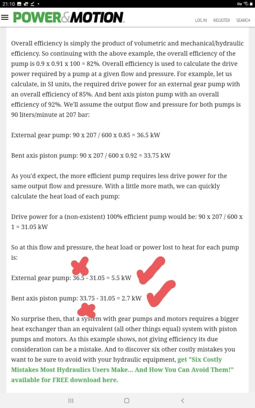
Screenshot_20220313-211053_Brave_sivqgn.jpg


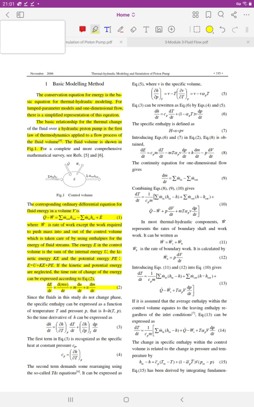
Screenshot_20220313-210159_Foxit_PDF_Editor_rjd7nj.jpg

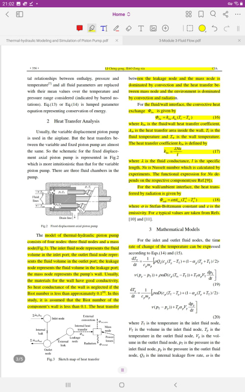
Screenshot_20220313-210209_Foxit_PDF_Editor_l2uzta.jpg

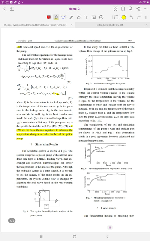
Screenshot_20220313-210236_Foxit_PDF_Editor_coo9mv.jpg


A black swan to a turkey is a white swan to the butcher ... and to Boeing.
 
Alternatively, for the example quoted, temp rise in the recycle loop T-To = 16.4degC for F = 2kg/min.
@1503-44
The first of your attachments estimates the heat input to the pumped fluid when the pump is in full forward flow, ie zero recycle. The 2nd of your attachments also appears to me to be the thermal analysis of this pump when in full forward flow during startup.


In a gear or piston pump the inefficiency is mostly due to slip. With a low enough efficiency the OP may not even need a recirc as the case drain could be plumbed back to the reservoir or dumped.
 
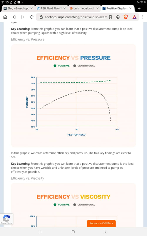
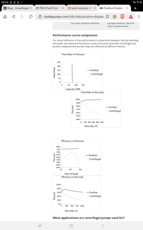
Tug, Exactly backwards, but the right conclusion. Yes PD pumps slip. Slip is accounted for by the Volumetric Efficiency Term. Total efficiency, what you see below, is Volumetric Efficiency X Mechanical Efficiency. As you can see, Total Efficiency is still hi across nearly full range of RPM. That's the real advantage of PD pumps. It is because of the HIGH EFFICIENCY of PD pumps at nearly all RPMs that recirculation may not be needed, as the useable work delivered is HIGH, heat generated is LOW. Why and how can you possibly say efficiency is low?

Eff_s_Pressure_-_PD_Centrifugal_gl1znz.jpg


Performance_curves_-_PD_Centrifugal_hkxypc.jpg


Georgeverghese, Where is your heat coming from? If you think there is forward flow, that was not stated in the example, fine, put them on full recirculation all flow back to suction. Make an example problem of your choice. Pick a reasonable PD pump efficiency curve like those above. Post your calculations. I need to see how you arrive at your conclusions.


A black swan to a turkey is a white swan to the butcher ... and to Boeing.
 
1503, as I understand the OP's question, the pumps need to be tested under system conditions but the flow has nowhere to go. They could run the pumps against the relief valves but there will be ~125kW of heat generated across the relief valves. If these valves recirc back to the pump inlet they'll be adding 125kW of heat into the pump inlet. As others have said, only a small amount of the flow needs to be dumped to dissipate the heat and offset with makeup flow. The entire flow does not need to be dumped.
 
"If these valves recirc back to the pump inlet they'll be adding 125kW"

I think we just proved that the pump does not generate 125kW heat. Maybe 30% of that at worst will make heat at full power. You did not contest any part of My 03:45 post above. If 125 kW is not generated by the pump, how does it appear at your valve? Do you think flow across the valve is a heating process, or what? Sorry, I dont get what you are saying. Could you please explain?

A black swan to a turkey is a white swan to the butcher ... and to Boeing.
 
We didn't prove the pumps don't generate 125kW heat. They do generate 125kW heat. All mechanical process eventually result in 100% of their energy becoming heat. Pump efficiency describes the amount of heat generated in the pump casing. Where else does the rest of the heat go? If it's doing mechanical work then that removes heat from the fluid flow. But, in the case of a recirc, there is no work done and all work is wasted. That means it becomes heat in the fluid. All of the pump work is lost. The system is 0% efficient even if the pump is running at 92% efficiency.
 
@1503-44, Maybe this will help:
Flow across a throttle valve is isenthalpic.
H1 = H2
ie
U1 + (PV)1 = U2 + (PV)2
For a high pressure liquid being depressured across a recycle valve (without a phase change, ie no flashing), decrease in the PV term has to reappear as rise in U, hence U2 > U1. This internal energy increase shows up as increase in T - for the entire PV change that was first enabled at the pump. So regardless of pumping eff, all of the work done by the pump reappears as low grade heat at suction during recycle. Its clear from the attachment you first posted(though not explicitly stated) that the case being analysed is not for a pump in full recycle.


Water inventory in pulsation dampeners/bottles in the pump suction or discharge within the recycle loop should not be included in the value for M in the expression derived for temp rise T-To, since these dampeners are connected to the recycle loop piping through a short branch off a piping tee, through which heat transfer would be poor.
 
I've had some time to think about this and to reboot a couple of times. Fortunately I've had good software to keep track of temperatures for me, but I can see now that I've been letting it do a little too much thinking for me. Thanks to both of you for your help.

A black swan to a turkey is a white swan to the butcher ... and to Boeing.
 
So is everyone happy with the Power Motion page posted 13 Mar 22:20 where the heat is generated by the 5.5 and 2.7 kW components? Is this a characteristic of only PD pumps?

If so, it must follow that we only need to consider full driver (shaft) power for heating when forward flow is stopped. Yes? Now if we opened to a partial recirculation of 30% of total flow through the pump, assuming the efficiency of the PD pump is relatively constant when recirculating and driver power remained at 36.5kW, then does it make sense to calculate temperature rate of increase of the recirculating stream based on 30% of the 36.5kW full driver power applied to heating the recirculation stream and calculating the temperature increase of the forward flow stream using 70% of the 5.5kW as heating the forward flow?

Plus, I stumbled on to this. Can anyone comment on those formulas.

A black swan to a turkey is a white swan to the butcher ... and to Boeing.
 
Those formulae are all examining temperature rise IN the pump. They do not account for temperature rise in the system where the bulk of it occurs.
 
I cannot believe that we are still discussing this. In a full recirculation loop, no "work" leaves the loop. All "work" is converted to heat and can only leave though the pipe wall by conduction though the wall. This is the problem the Op has to solve. A fractional flow of water to the drain allows this heat to be removed by the draining water. It really is as simple as that.
 
Status
Not open for further replies.

Part and Inventory Search

Sponsor