Eng-Tips is the largest engineering community on the Internet

Intelligent Work Forums for Engineering Professionals

  • Congratulations waross on being selected by the Tek-Tips community for having the most helpful posts in the forums last week. Way to Go!

re. impedance measurement for three phase motors 3

Status
Not open for further replies.

AkaShri

Mechanical
Mar 30, 2022
8
0
0
IN
Hello everyone,
For a delta three phase motor, how to calculate impedance (and impedance unbalance) with three phase current and voltage measurement at motor control center ? Do we have to divide RMS line voltage with RMS current ? How the impedance unbalance related to motor efficiency loss, is there any formula ?
 
Replies continue below

Recommended for you

Akashri: If you're making the measurement at the motor control center, you have no idea whether the motor winding is unbalanced. This is because you are also measuring the impedance of the cabling (and any other gear) between your point of measurement and the actual winding - which terminates in the junction box beside the motor itself.

That being said: (Impedance per phase) = (voltage per phase) / (current per phase)

Percent unbalance is calculated for each phase (usually voltage and current and impedance).

(percent unbalance) = 100 * (absolute value of the difference between the actual phase value and the average value of all three phases) / (average value of all three phases)

Usually some unbalance exists. If enough is present, it usually indicates a winding issue - which means something is wrong with the motor. Parts are working harder than they should, so it is less efficient in the big picture.

Converting energy to motion for more than half a century
 
Thanks Gr8blu,
At motor control center we can only measure three conductor currents (line currents), can we calculate impedance for Delta connected motors ? Phase voltage is different than what we are measuring!
 
AkaShri: See previous post. If you're only taking measurements at the Motor Control Center (MCC), then you CANNOT determine the motor's impedance values, because there is more than just the motor's winding impedance(s) in the circuit.

As to phase vs line values - remember the basic relationships for three-phase systems.
WYE CONNECT: Vphase = Vline and Iphase = Iline / 1.732
DELTA CONNECT: Vphase = Vline / 1.732 and Iphase = Iline

Converting energy to motion for more than half a century
 
I have to ask, for what purpose are you trying to measure impedance?

Even if you could measure direct at the motor terminals, it doesn't seem to be a useful indicator of motor condition
[ol 1]
[li]The real component varies heavily with load (unrelated to motor condition).[/li]
[li]The reactive component does not vary predictably in any manner related to normal sustained faults. If you experience turn to turn short, the condition will very likely escalate quickly to ground fault and trip. [/li]
[li]The effects of any voltage unbalance can NOT be eliminated by a simple per phase impedance calculation. First let's look at the load current. The phase that sees the lower voltage can draw the higher load current component, so the apparent impedance in each phase is varying dependent on the voltage imbalance rather than the motor characteristics for a loaded motor. Now let's consider an unloaded motor, the current unbalance is way higher than the voltage unbalance so it's not a straightforward per phase impedance calculation (you'd need to look at a symmetric components model). [/li]
[/ol]

So again it's not clear to me what you are really trying to accomplish. I guess I can see there might be potential value searching for high resistance connections anywhere in the supply path to/through the motor. I'd have to think some more about what's the best way to do that. Initial thought is first step look for current unbalances, and then if you see something unusual to do further analysis if you find those to try to figure out what it represents by examining voltage unbalances at various points in the system.


=====================================
(2B)+(2B)' ?
 
Thanks @Gr8blu for your response. I guess WYE should be DELTA and DELTA should be WYE.

@electricpete - thank you for your comments.
I was interested in impedance unbalance calculation as there is a relation between impedance unbalance and loss in motor efficiency (exact relation I am looking for; some graphs are available online -
I have also seen that online analyzers report this value. Now my doubt is - if we are measuring three phase voltage (using voltage dividers) and three phase currents (using CTs installed at three conductors) at motor control center, how to calculate impedance ? Since in delta connected motors, conductor current divides into two of the windings. I have similar doubt for power factor calculation too. Can we calculate true power of motor using above mentioned measurements ?
 
AkaShri said:
Now my doubt is - if we are measuring three phase voltage (using voltage dividers) and three phase currents (using CTs installed at three conductors) at motor control center, how to calculate impedance ? Since in delta connected motors, conductor current divides into two of the windings.

That would involve a vector calculation which would require relative phase of the currents. If you had such phase, you could calculate the vector current flowing in each leg of the delta winding from the vector currents flowing in the line. Then you could calculate impedance by comparing the current in each delta leg with the associated phase to phase voltage.

But I doubt you have relative phase measurements of your currents. And further even if you had that relative phase info, I don't think you should waste time trying to calculate phase impedance of a running motor. I haven't seen that done. If analysers do it, they probably do it because it's easy, not because it's useful. I'm not impressed with the blogger you quoted.

To be sure, there is a lot of modeling that can be done to estimate efficiency (from running measurements and nameplate and motor test data). Unbalance certainly plays a big role. I'm not sure how you get there with simple impedance measurements. If you want to build a model involving impedances, a sequence model would be best (positive sequence and negative sequence).


=====================================
(2B)+(2B)' ?
 
In most cases it is safe to assume the cause of current unbalance under load is voltage unbalance. This is a pretty good link showing effects of voltage unbalance (measured at the motor) upon motor performance here.


=====================================
(2B)+(2B)' ?
 
electricpete said:
I'm not impressed with the blogger you quoted.
In particular this one: Why is Impedance Imbalance for Electric Motors so important.

Let me elaborate:
blogger said:
Why is Impedance Imbalance for Electric Motors so important.
Saturday, April 4, 2020
The analogy is liking it to Running a car for long periods of time with, out of balanced tyres.

Impedance imbalance is the electrical equivalent of getting your tyres balanced, its saves energy, reduces wear & tear, and risks other damage like suspension & steering. So what is it????

Impedance is the load the electrical supply sees when running an electric motor. And it uses alot!!!!

47% of global electricity consumption is use in motor systems.

Take a cooling tower motor which runs continuous, it will typically uses 16x its purchase value in energy annually. Based on 9.7 euro cents per kWhr.

The motor manufacturers produce motors to a standard eff2 or eff3 which has an appproximate efficiency of 90+% for motors and 95+% for motors above 100kW. Alot of factors can eat away at this efficiency when installed, such as motor loading, harmonics, mechanical losses in impellors, alignment, and balancing. 
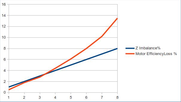
You may not be aware but Impedance imbalance is a big factor, a 3% imbalance leads to approximately 3% efficiency loss, but a 6% imbalance is closer to 8% loss. Most of the losses end up as heat decaying Motor Insulation, Terminations and Switchgear and if left without remedy propagate to a failure.
impedanceimbaleff_doetyv.jpg


Impedance Z is the total resistance of a motor circuit and is made up of Resistance R, Reactance XL, and Capacitance Xc. The R componentis usually made up of cable and coil resistance but can be elevated by burnt contacts, poor crimps, corroded or poor terminations, and makes up the dominant portion of defects. XL is the motor winding impedance, defects from new or overhauled motors effect imbalance. Xc is the capacitance component dominanted by cable and contamination factors.

Conducting Motor Circuit Analysis will identify these imbalances and be remedied, but defects in Overhauled or New Motors means your stuck with them for the life of the motor (Probably a shorten life). Setting a purchase/ovrhaul specification and conducting acceptance testing serves as a filter, stops them entering your plant and someone else is likely to get them.

The rejection rate can be significant, and even if you have to pay a premium the cost will be recouped rapidly in energy & reliability savings.

3Phi Reliability Motor Health Assessment use the ALL Test Pro 31 to make these measurements, and analysis of a motor circuit can be completed within minutes.
I am kind of speechless. He defines the impedance he's talking about... it depends resistance and inductive impedance. And it also depends on a capacitive impedance? But more importantly, there is no slip!?!

The only picture I can cobble together to explain such gibberish is that the author views an electric motor as a network of impedances that may be unbalanced. And apparently it is connected to a balanced voltage source, and the resulting currents vary in inverse proportion to the impedeances (I = V/Z). This neglects the effect of slip in determining the effective impedance while operating. It neglects the fact that motor current unbalances more often originate from supply voltage unbalances (rather than from motor impedance unbalances). It neglects the fact that the high slip associated with the negative sequence circuit means that the negative sequence impedance is far lower than the positive sequence impedance.

I see there is similar line of reasoning in another presentation associated with All-Test Pro here. It is equally gibbberish.

I feel bad picking on these guys who are not here to defend themselves. It is what it is. My advice to you is ignore these resources and look for more reliable resources.


=====================================
(2B)+(2B)' ?
 
Thank you very much @electricpete for the detailed information.
It is very difficult sometimes to get to the reliable sources. We cannot ignore when they publish results based on some study (real or simulated). I would be grateful if you can share some docs or links on online motor monitoring where three phase currents and voltages are captured for power quality analysis, electrical and mechanical fault detection.
 
We cannot ignore when they publish results based on some study (real or simulated).
Is there any study behind the blog post that you linked? I don't think there is. I saw a graph. Where did the graph come from ? No one said.

I would be grateful if you can share some docs or links on online motor monitoring where three phase currents and voltages are captured for power quality analysis, electrical and mechanical fault detection.
Motor power monitoring is a broad subject. I don’t claim to be an expert on all aspects of it. I have been responsible for the motor monitoring program at our plant (it's a power plant) for over two decades. At our plant, beyond simple monitoring of current as indirect indication of loading, the only motor monitoring function that we have related to power analysis is looking for broken rotor bars (by performing an FFT of the current spectrum and looking at the magnitude of pole pass sidebands around line frequency). That doesn’t mean there are no other useful applications of power monitoring of motors, but I have found them of limited benefit, at least for our applications.

There's a lot that could be said about motor monitoring, but I'll stick with the original topic of voltage and current unbalance in motors. The first link that I provided provided before is a relatively accurate and simple summary imo:The Influence of Voltage Unbalance on NEMA Motor Performance. Within that link, I recognize that Figure 1 (NEMA derating curve) and Figure 2 (Effect of unbalance on polyphase induction motor) are both taken from NEMA standards (even though they didn't annotate them as such). And NEMA has referenced studies to support those (I have tracked them down before, most are copyrighted).

If you have an appetite to understand the basis for the Figure 1 derating curve from the first link, the screenshot below is a spreadsheet I created awhile back to help me understand the logic built into that graph. It references something from a Nailen publication, I'll add that part later.
Screenshot_2022-04-14_100827_qh52z0.gif


If you have an appetite to understand why figure 2 of that first link looks the way it does, there is a relatively straightforward (albeit theoretical) explanation given at a second link here. Basically it is just applying the induction motor steady state equivalent circuit to both the positive and negative sequence circuits, with different slips (Figure 1 of that 2nd link)

IF your company happens to be a member of EPRI, another useful document related to effect of voltage unbalance on motors is EPRI 3002005358


=====================================
(2B)+(2B)' ?
 
I'll add one more thing. When you read the literature you see that maximum deviation from average (as a fraction of average) is treated as a proxy for negative sequence (as a fraction of positive sequence). It falls from the assumption that there is no zero sequence present (which applies the set of three phase-to-phase voltages whose vectors form a closed loop starting where they ending, and also applies to current flowing into any power system load that doesn't have a ground in it). With these assumptions, a numerical check confirms V-/V+ is almost exactly equal to the (Vmax-Vmin)/Vavg.


=====================================
(2B)+(2B)' ?
 
Again - if the measurement is taken at the MCC, there is NO WAY to determine the unbalance effects on the motor by itself - and thus no way to determine the efficiency impact based on what you are measuring. Further, if the voltage and current measurements do not include phase (angle) data, there is no way to calculate what is really going on in terms of unbalance.

Resistance is pretty easy, since it is essentially linear (with temperature, mind you, but linear). Inductance and Capacitance are not so easy, since they get affected by frequency as well . . . which means all those pesky harmonics are also in the mix. Add in switching frequencies if you're on a drive, too.

I do agree with electricpete's post from 14 April at 1546h. The negative sequence is proxied by the max deviation from average. Not always a perfect relationship, but close enough for most non-laboratory purposes. Certain machine types and windings show more variability, but the assumption holds fairly consistent when looking at the (relatively) simple squirrel cage induction motor.

Reviewing some of the earlier posts - most of the "use our tool to monitor/measure what you need to know" discussions have a "tuned" approach. What this means is they have their internal software calculations based on a predetermined data set of machine "geometries" . . . and once you get outside their experiential database, all bets are off regarding accuracy of results. For example: I have direct experience with two such systems - both of which get the conclusion right about 60% of the time on machines that correspond to the collected database. And are 95% WRONG when something is a "new" subject - like a new winding, a different manufacturer, a different insulation system (resins and/or tapes), metric vs imperial "base" geometry, and so on.

Converting energy to motion for more than half a century
 
Status
Not open for further replies.
Back
Top