Continue to Site

Eng-Tips is the largest engineering community on the Internet

Intelligent Work Forums for Engineering Professionals

  • Congratulations IDS on being selected by the Eng-Tips community for having the most helpful posts in the forums last week. Way to Go!

Reached the limit for the number of nodes.

Status
Not open for further replies.

OJM

Civil/Environmental
Dec 15, 2016
33
Hi all,

I have a question,

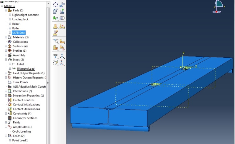
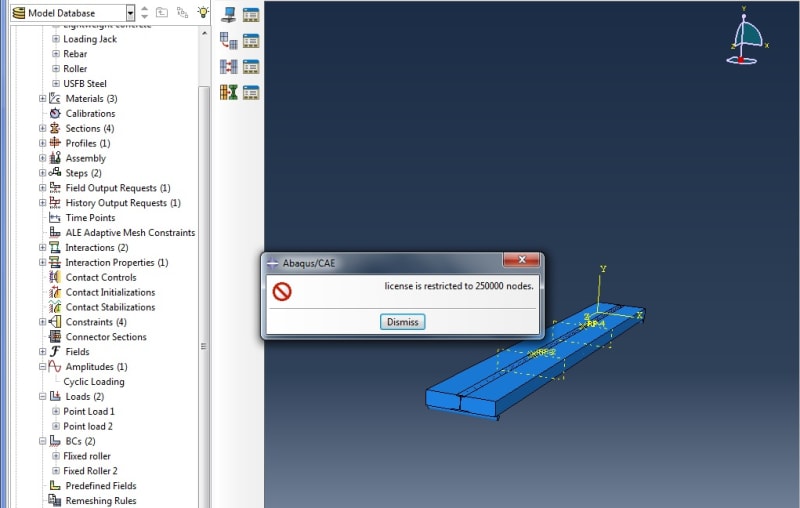
how can I reduce the number of nodes that I have for my model. It's quite a large beam (7.2m long with a 1m wide slab) and it says I have exceeded the 250,000 node limit and can't run it. Someone mentioned that I may be able to mirror it and thus cutting out half the structure (as it is symmetrical in two planes). How would I go about doing this? Also I can't seem to find a way to find the number of nodes that I have in my structure, how do I find this?

Please find attached model,
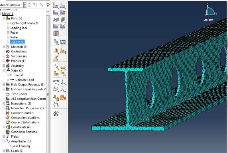
Untitled_ox8dme.jpg

Untitled2_mf2tg3.jpg

Untitled3_zu4nyk.jpg


Thank you very much for the help,
 
Replies continue below

Recommended for you

When you model a beam with solid elements you need at least 3 elements through thickness to capture stresses correctly. In case of limited license I suggest using shell model. Beam elements won't be sufficient because of these holes.
 
The model seems to have two symmetry planes, so a quarter would only be needed. Cut the unneeded geometry away in the part-module.
Don't forget to apply the symmetry boundary conditions in the loads-module.
Use Partitioning to make the regions hex-meshable. Use Incompatible-Mode Elements C3D8I when the elements don't deform in a large way.
Use Tools -> Query -> Mesh to get mesh statistics.

Shell elements are an option for the beam. But then I would apply them as skin directly at the hex elements of the block and use an offset for the shell thickness.
 
So I cut the beam in half and applied a symmetric boundary condition, good news it works! (under 250,000 nodes).

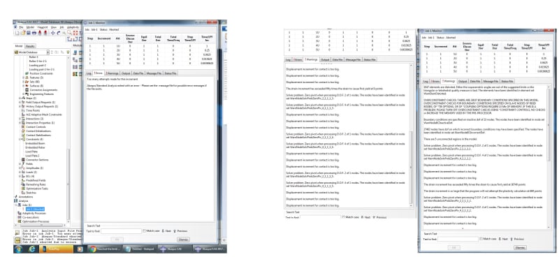
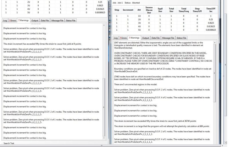
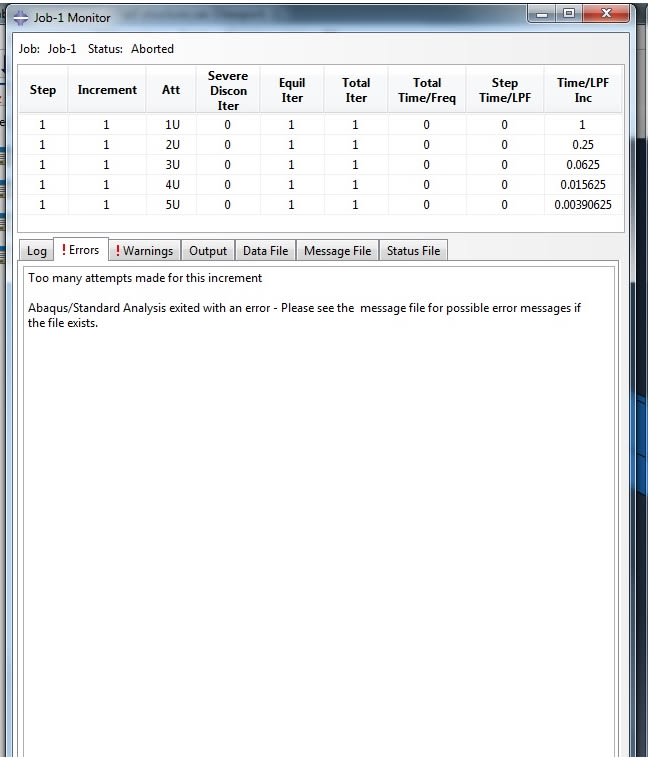
I have got a lot of errors, I think my beam mesh is wrong, I have used Hex elements and meshed the whole thing without partitions as partitioning would be hard with all the holes.

I have restrained the reinforcement bar through the holes at the ends in the X and Z directions, (I want the rebar to move when the beam bends but stay embedded in the concrete with embedded region) So i don't know why I am getting this stupid Zero pivot error.

Abaqus_Problems_u4qb8r.jpg


Would anyone be able to open it up and see if they can make it run? I would be so greatful.

Many Thanks

 
Abaqus_Problems1_zodgp5.jpg


Abaqus_Problems2_lu1kph.jpg


Sorry about the small images
 
Did you use embedded region constraint ? These errors suggest that something is unconstrained. Make sure that no part can move freely. You can use eigenfrequency extraction analysis to check that.
 
Yes embedded region was used for the rebar, I constrained the ends of the rebar in two directions (not 3) should this be enough?

I'll look into doing eigenfrequency extraction analysis is this hard?
Thanks
 
All rigid body motions must be blocked for each part. For 3D elements there are 3 degrees of freedom (translations in XYZ directions) and they should be fixed.

Eigenfrequency analysis is very easy to perform. Just replace your static step with Linear perturbation —> Frequency, select the frequency around which the solver will be searching for natural frequencies or specify their number. Then suppress load leaving BCs as they are. Add density to the material definition so that the mass matrix can be formed. Then run the analysis (it should complete quickly) and examine calculated mode shapes.
 
I have blocked all the different parts in XYZ directions and increase the reduced the increment in my amplitude table of loads and still give the same errors.

Any idea?
 
Beam and shell elements in 3D also have 3 rotationa DOFs (4-6). Try using automatic stsbilization in the step and use eigenfrequency approach to find any rigid body motions.
 
Status
Not open for further replies.

Part and Inventory Search

Sponsor