Eng-Tips is the largest engineering community on the Internet

Intelligent Work Forums for Engineering Professionals

  • Congratulations waross on being selected by the Tek-Tips community for having the most helpful posts in the forums last week. Way to Go!

Reaction forces acting on pipe discharge submerged underwater 1

Status
Not open for further replies.

abot93

Mechanical
May 21, 2020
10
0
0
US
Hello All,

We are installing new vertical turbine pumps on a river water intake structure. The client did not want VFDs so we have minimum flow recirculation lines off each pump that pipe back down into the river. The discharge of these recirc lines is below the river water level. I have talked to several engineers in my company who feel that this setup will create a reaction force against the pipe supports, and that we have basically created a jet nozzle. Looking for insight from anyone who has had a similar project, or can comment on whether there will be a reaction force from this setup.

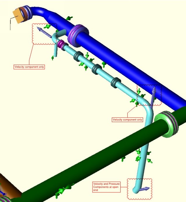
For reference, the min. flow recirc. lines will have 3,000 gpm exiting through a submerged 14", 45 elbow off a straight vertical leg of pipe aimed down at the river (approx. 7 ft/s velocity). There are restriction orifices in the recirc. lines to bring the fluid pressure down to be close to 0 psig before exiting. I have used the equation that defines the relief valve discharge reaction for non-flashing liquid to approximate the reaction force.

Recirc_lines_blm8dh.jpg


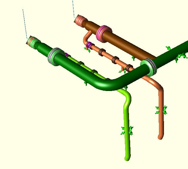
The image shows some of the relevant piping layout with the recirc lines coming off of the main pump discharge lines.

Again, any insights or references are more than welcome and additional information can be provided if needed.
 
Replies continue below

Recommended for you

Yes there will be a reaction force.
Are you trying to make us guess what force you calculated?


“What I told you was true ... from a certain point of view.” - Obi-Wan Kenobi, "Return of the Jedi"
 
I'm not trying to make anyone guess, but I had several different equations I have been referred to that are orders of magnitude different.

1) Using the API 520 Relief Valve Discharge Reaction for Non-flashing liquid (F = W/366*sqrt(k*T/((k+1)*M)) +A*Po) I get a 15,725 lb resultant force. From API 520, "formula is based on a condition of critical steady state flow of a compressible fluid that discharges to the atmosphere through an elbow and a vertical discharge pipe", which doesn't sound like this setup at all. The force is also staggeringly high in my eyes when the pressure difference between the discharge and the river aren't that extreme.
2) Using the Jet Discharge Propulsion equation from engineering toolbox (F = ρ*A*v^2) I get a 91 lb resultant force. This resultant load isn't even worth bringing up to structural.
3) Using the thrust block forces on pipe bends equations from engineering toolbox I get a 1653 lb resultant force. I understand that with welded steel pipe the welds/elbows will contain these forces, but since one of my ends is open I could see how this may apply.
4)The pressure differential between the pipe discharge and the river ranges from 5-15 psi depending on the water level elevation. If the cross sectional area is about 140 in^2, then the force required to cover the pressure difference is between 700-2100 lbs. This lines up most closely with the thrust block equations, at least in order of magnitude.

I have not been able to even find a source that clearly defines this type of problem, and the fact that one of the equations I have been suggested to use would require serious structural considerations for a high horizontal load I am obviously concerned about what to tell them for the restraint loads.

Again, if anyone has worked on something similar or has any comments/questions about this post I will be more than happy to provide what I can.
Thanks.
 
The one fixed pressure here in the abbreviated system you are talking about is a known value at the discharge outlet (5-15 psi) as you say, "depending on water level. You don't say if you are using PSIG or PSIA, it should be psiA. Because atmospheric pressure is 15 psia, you probably don't have the 5-15 psi you are talking about. What you really have is atmospheric pressure on top of water pressure, 15 psia, then you add the river water pressure, 33 feet of which equals 15 psia, so assuming you made that mistake, I think you might have water levels 10 to 30 feet over your outlet, which is really an ABSOLUTE outlet pressure of 20 to 30 PSIA.

Secondly, the hydraulics. I don't think that you are helping anything with your, "restriction orifices in the recirc. lines to bring the fluid pressure down to be close to 0 psig before exiting." You don't have any control of that, as it is controlled by atmospheric pressure and river water level. No matter what you do inside your pipe system, the outlet pressure will not be affected, it will be between 20 and 30 psiA. That's a fixed value, so to speak, which your hydraulic system must contend with. Therefore it is not the outlet pressure that is the unknown value in your hydraulic pressure loss and flow calculation. It is the upstream pressure that is the unknown, or, if your upstream pressure really is held constant by the pump discharge pressure, then it is the flowrate that will have to be calculated based on that pump discharge pressure and the pressure at the outlet in the river. In that respect, your restriction orifices will not do anything useful. They will tend to increase the pump discharge pressure, if the pump can put out a higher pressure, or if the pump is at max discharge pressure, the added restrictions will simply decrease the recirculation flowrate because of their additional resistance to flow that they add. You may also have increased the exit velocity because the restrictions might decrease the effective outlet area of your nozzle, which could increase thrust. You should increase pipe and nozzle diameters in order to decrease thrust.

For reaction force calculation see B31.1. It uses internal pressure just before the outlet, rather than the Engineering Toolbox formula. Those guys over there are programmers not engineers. They gave you the formula you used, but then they worked their example problem using a different formula, not giving velocity, so hard to check what they have there.

With the numbers you did give above, I had to estimate the internal pressure and I used 35 psiA and a 25 psiA river water pressure and got a value of 1500 lb force at (all nozzles, if there are more than one). To that, and according to B31.1, you should consider safety factors and double that value to get a static load equivalent of that very dynamic load. so (using those pressures) I get 3000 lbs as the equivalent static design load on each nozzle. Why don't you direct the nozzles in opposite directions and when both are flowing, the net force on the structure will be ZERO, and only 1/2 of my total when only one nozzle is flowing. BTW what is your internal ABSOLUTE PRESSURE?


“What I told you was true ... from a certain point of view.” - Obi-Wan Kenobi, "Return of the Jedi"
 
@ax1e,

Thanks for coming back with this response. I appreciate it. I've had to reread this a few times, so correct me if I'm wrong with the following.

At the river's minimum elevation, the difference in height between the nozzles and the water's surface is 2 feet. So the minimum outlet pressure is about 15.5 PSIA, and the most it will ever be is 21 PSIA at the river's highest point.

For the internal absolute pressure, I'm not sure this is correct, but this is my understanding of it so far after talking with one of the process engineers. So the selected pump curve has a design flow of 10,000 GPM at 130 TDH (ft) for when the pumps are running through the main 30" lines. If they don't require water upstream, they can close off the 30" lines and pump water through the smaller recirculation lines to keep from turning these large pumps on and off as often. The recirculation lines were designed to back the pump up the curve to the minimum flow requirement of 3000 GPM at 208 TDH (ft). I've been told by process that the control valves and three restriction orifices each drop the internal pressure in the pipe so that the internal absolute pressure after the last restriction orifice is 9.3 PSIA. The pipe goes down for 20' before the outlet to the river, so the internal absolute pressure in the pipe before reaching the outlet should be about 18 PSIA if I understand the hydraulics correctly.

These pumps are running one at a time, and the nozzles are pointing the way they are to help minimize erosion on the shore, so I can't do much to zero out the net force on the structure. That was still a clever idea, though.

From the formula provided above:
It looks the first term handles the velocity component, which is very small in this case (417 lbm/s)/(32.2 ft/sec^2)*(7 ft/sec) = approx. 91 lbf.
And it looks like the second term handles the pressure component, where the pressure difference between outlet and internal is what counts (18 PSIA - 15.5 PSIA)*(137 in^2) = approx. 350 lbf at the river's lowest. Using the same for the river's highest yields the negative value of approx. -420 lbf. (I'm assuming that the sum of the velocity and pressure components can be modeled as one force vector at the outlet, perpendicular to the outlet's cross-sectional plane??)

If this is correct, then the safety factor of 2 puts the static design load at around 1,020 lbf.

Again, thanks for the guidance @ax1e. If you could let me know that I'm on the right track or if there's still something off about this I would greatly appreciate it.
 
Looks right until you get to the -420 lbf.
That was what I was trying to get at before with the hydraulics explanation. Internal pressure 18 psia must be higher than external pressure 21 psia, else river water tries to flow into the outlet, backing up recirculation flows. The recirculation flow will drop, which tends to reduce pipe friction, allowing the the outlet pressure to increase to equal the 21 psia, at which time recirculation flow will begin again, but at a lesser rate than 3000. In which case you may try to increase the pump discharge pressure (if possible) to regain your 3000 gpm recirculation rate.

With high river level the external pressure is a known pressure of 21 PSIA, the 3000 gpm is a known flowrate, so you solve the hydraulic equation for the pipe's friction loss using 3000 gpm and you add that piping pressure loss to the 21 PSIA, along with all the rest of the restriction orifice losses and the control valve losses to arrive at the pump's minimum discharge pressure to hold that 3000 gpm flow rate. If the pump can reach and operate at that minimum discharge pressure, you will get 3000 gpm going into the river. If the pump discharge pressure goes higher than that, then you will get more than 3000 gpm going into the river, unless you can close the control valve some more to increase the pressure drop once again and thereby hold flow to 3000 gpm.

“What I told you was true ... from a certain point of view.” - Obi-Wan Kenobi, "Return of the Jedi"
 
My apologies to both @ax1e and @bimr for the late response,

bmir,
The momentum equation provided is analogous to the velocity component of the reaction force equation found in B31.1 . Thank you for providing the additional information as well, I have not found this unbalanced hydraulic force at a pipe intersection referenced in any of my past research.

ax1e,
After speaking with our process group, I realized that I discounted the fact that both the pump suction and pipe discharge are coming from the same source of water. If the river level rises it should increase both the pressure in the pipe and the outlet pressure to approximately maintain the same pressure differential, with minor changes from the increases friction losses in the pipe at higher pressures.

I've attached a photo with locations that have forces applied on the discharge piping and whether the velocity and/or pressure components of the equation have been applied.
Piping_discharge_reaction_forces_gksdib.jpg


Again, very appreciative of both of y'alls responses.
 
It is usually the low river level that creates the most trouble, as that is the critical case for suction pressure.

Nice to have mother nature cooperating for a change!


“What I told you was true ... from a certain point of view.” - Obi-Wan Kenobi, "Return of the Jedi"
 
Status
Not open for further replies.
Back
Top