Hello All,
We are installing new vertical turbine pumps on a river water intake structure. The client did not want VFDs so we have minimum flow recirculation lines off each pump that pipe back down into the river. The discharge of these recirc lines is below the river water level. I have talked to several engineers in my company who feel that this setup will create a reaction force against the pipe supports, and that we have basically created a jet nozzle. Looking for insight from anyone who has had a similar project, or can comment on whether there will be a reaction force from this setup.
For reference, the min. flow recirc. lines will have 3,000 gpm exiting through a submerged 14", 45 elbow off a straight vertical leg of pipe aimed down at the river (approx. 7 ft/s velocity). There are restriction orifices in the recirc. lines to bring the fluid pressure down to be close to 0 psig before exiting. I have used the equation that defines the relief valve discharge reaction for non-flashing liquid to approximate the reaction force.

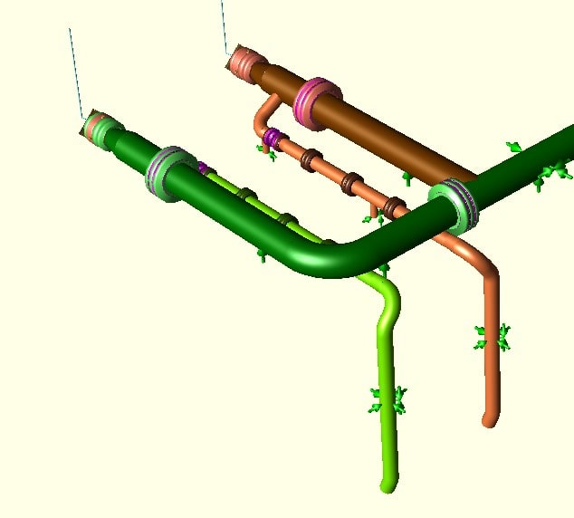
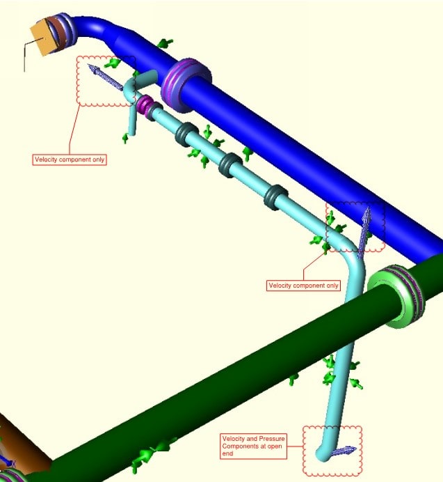
The image shows some of the relevant piping layout with the recirc lines coming off of the main pump discharge lines.
Again, any insights or references are more than welcome and additional information can be provided if needed.
We are installing new vertical turbine pumps on a river water intake structure. The client did not want VFDs so we have minimum flow recirculation lines off each pump that pipe back down into the river. The discharge of these recirc lines is below the river water level. I have talked to several engineers in my company who feel that this setup will create a reaction force against the pipe supports, and that we have basically created a jet nozzle. Looking for insight from anyone who has had a similar project, or can comment on whether there will be a reaction force from this setup.
For reference, the min. flow recirc. lines will have 3,000 gpm exiting through a submerged 14", 45 elbow off a straight vertical leg of pipe aimed down at the river (approx. 7 ft/s velocity). There are restriction orifices in the recirc. lines to bring the fluid pressure down to be close to 0 psig before exiting. I have used the equation that defines the relief valve discharge reaction for non-flashing liquid to approximate the reaction force.

The image shows some of the relevant piping layout with the recirc lines coming off of the main pump discharge lines.
Again, any insights or references are more than welcome and additional information can be provided if needed.

