Continue to Site

Eng-Tips is the largest engineering community on the Internet

Intelligent Work Forums for Engineering Professionals

  • Congratulations KootK on being selected by the Eng-Tips community for having the most helpful posts in the forums last week. Way to Go!

Reaction forces of moving SCARA robot

Status
Not open for further replies.

SC83

Mechanical
Jun 8, 2018
24
Dear,

I have to design a table for a SCARA robot which will be mounted on top of this table. I'm not allowed to bolt the table (consisting of 4 legs bosch frame and aluminium top plate) on the ground (drilling of holes in the ground is not allowed). I need to know if the table will stand still or shake/move under the acceleration forces of the robot. The table should also not tip over under the acceleration forces of the robot.

I have a NX design of the table with top plate. In the top plate are four mounting holes for mounting the SCARA robot.
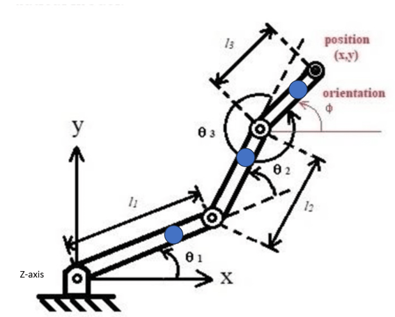
The SCARA robot consists of three joints/arms - see attached - and translates/rotates the end effector in the XY-plane.
I have the masses of the three arms, their lengths and their COG. I know the max. linear (radial) acceleration and rotation (theta) acceleration. I don't have detailed/CAD model of the SCARA robot.
I also know the reaction torque of the motors which rotate the arms.

How should I model this in ANSYS? I only need to check the worst case situation, i.e. stretched arm.

I have a license for static structural and modal analysis in ANSYS. Any suggestions are welcome.
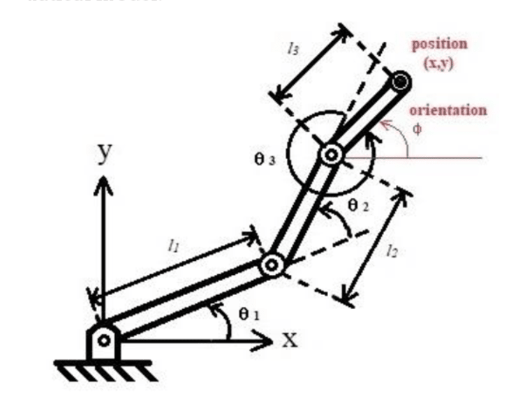
SCARA_robot_frhgmj.png

Regards,
SC
 
Replies continue below

Recommended for you

forget the table ... I'd be worried about the interface between the robot and the table if all I have is gravity. Where's the CG of the thing (like with the arms fully extended)?

"Hoffen wir mal, dass alles gut geht !"
General Paulus, Nov 1942, outside Stalingrad after the launch of Operation Uranus.
 
Hi rb1957,

Why should I forget about the table? If the inertia of the robot arm is too large then the table could move/dance on the floor as it is not bolted to the floor.
I check also the load on the interface between the table and the robot in Ansys.
The COG of the three arms together will be somewhere near the rotation point of theta 3 when the arm is fully extended.
FYI: the picture above is the top view so the scara motor cannot move in the vertical direction.
 
yes it's possible the table will "dance" but it is more likely that the robot will fall over (first).

if the CG is out by theta3, then how big is the base of the robot ? (bigger than theta3 ?)

what is the mass of the robot ? the weight/load expected ??

"Hoffen wir mal, dass alles gut geht !"
General Paulus, Nov 1942, outside Stalingrad after the launch of Operation Uranus.
 
If I understand this correct you have three arms moving in the xy-plane. That means that there will be inertia forces in the xy-plane. And then you have gravity acting in the negative z-direction.

I suppose that one option is the work with 3 beams under gravity load and add the inertia effects as static loads. It may be sufficient to see if the design is reasonable.

Since you seem focused on tools (like ANSYS) I suspect that to solve this best you would need a software that can handle kinematics.
 
Hi ThomasH,

Yes, the three arms move only in the XY-plane by rotation of the arms around theta 1, theta 2, theta 3. The gravitational force is in the negative Z-direction.
I have defined the mass of each arm in its COG wrt the XYZ-cordinate system (indicated by the blue dots below) using point masses in Ansys.
Now, I have to define the moment of inertias for each arm. Is the following reasoning correct:
[ul]
[li]I_arm_1_Z = I_arm_1_COG + m1.r1^2[/li]
[li]I_arm_2_Z = I_arm_1_COG + m2.r2^2[/li]
[li]I_arm_3_Z = I_arm_3_COG + m3.r3^2[/li]
[/ul]

I which r1, r2, r3 is the shortest disctance from each pointmass to the Z-xis.
Or should I define for arm_2 and arm_3 the distance r2 and r3 wrt to their own rotation point, i.e. the joint_theta_2 and joint_theta_3.
SCARA_robot_2_w64tpt.png
 
how the arms move is one thing, but I think it's more important to understand how the base pivot is constrained. It was a major point in the post to say "I'm not allowed to bolt the table" ... is there some base plate that you are clamping to the table, or is it just sitting there (with only gravity providing the "fixity") ?

If it is clamped then I think you can proceed with the dynamic analysis of the arms. If it is just sitting on the table, then I think you need to understand how much load you can apply before the interface gaps. Is the base plate particularly heavy, compared to the arms ?

Should this be posted in the "student forum" ?

"Hoffen wir mal, dass alles gut geht !"
General Paulus, Nov 1942, outside Stalingrad after the launch of Operation Uranus.
 
Yes, the robot is fixed to a base plate which is mounted to the table frame. The 4 legs cannot be bolted in the floor.
 
oh, ok ... misread, misunderstood.

I'd put a 25 lbs shot bag on each leg and call it a day.

"Hoffen wir mal, dass alles gut geht !"
General Paulus, Nov 1942, outside Stalingrad after the launch of Operation Uranus.
 
Status
Not open for further replies.

Part and Inventory Search

Sponsor