Eng-Tips is the largest engineering community on the Internet

Intelligent Work Forums for Engineering Professionals

  • Congratulations waross on being selected by the Eng-Tips community for having the most helpful posts in the forums last week. Way to Go!

Reaction forces on Cylindrical Composite Tube

Status
Not open for further replies.

jonny1230

Materials
Feb 7, 2015
14
GB
Hi all

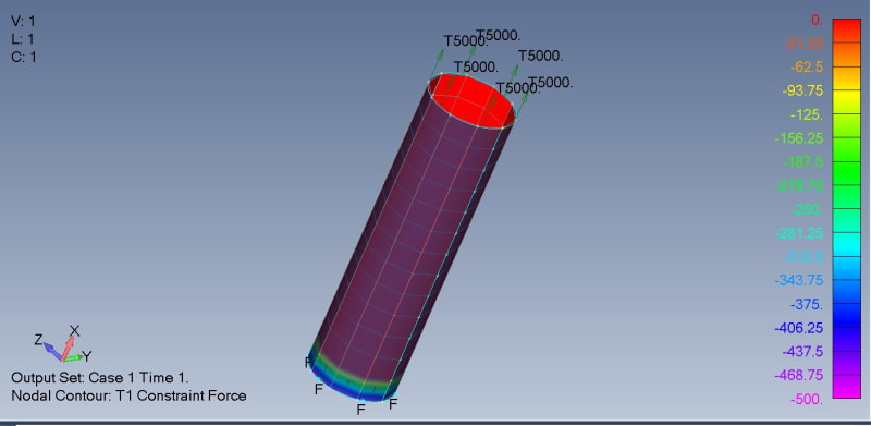
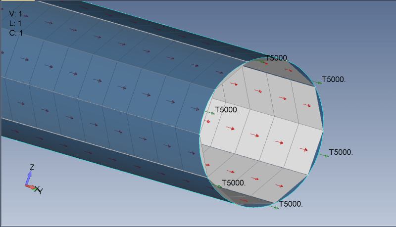
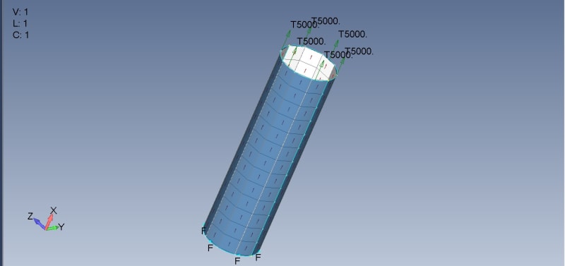
I am modelling a composite tube under tensile deformation. My material coordinates, and element coordinates are right. I have applied a tensile load of 5kN at one end of the specimen while fixing the other end.

I am not sure how to extrapolate the reaction forces. I am using the constraint forces that generate at the fixed end to determine the axial modulus, and using the maximum tensile displacement in x direction for calculating strains.

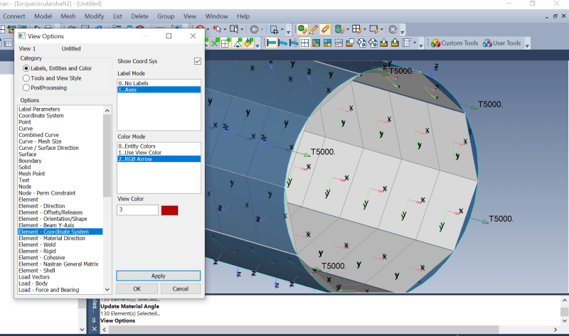
My axial modulus is coming out to be 5 times higher than it should be. I have a configuration of [0,45,-45] and which is impossible. I am using cylindrical coordinate system and have aligned everything along R direction

Can anyone advice ? I am attaching some images.
Stress_Countours_r7ucdp.jpg
material_direction_jr2iwd.png
Boundary_Condition_vx5qkv.jpg
coordinate_system_rhlh9i.png
 
Replies continue below

Recommended for you

is a fully fixed end what you really want, or is this over constraining the end ?

what is your element material direction ? The R direction ??

"I am not sure how to extrapolate the reaction forces." … this is linear FEA right ? that's a clue.

is this a student post ?? (looks suspiciously simple and much of what you've done seems irrelevant to the solution ?

another day in paradise, or is paradise one day closer ?
 
Hi, I am new to FEMAP, and have been using Ansys and Abaqus for years so hence this post. I am modelling a fibre reinforced tube with lay up [0, 45, -45] and the axial modulus is I am getting from the model is not matching with my analytically solved value (which is correct). I am mimicking the a tensile test of composite tube.

Unlike other FEA softwares, where I can extrapolate reaction forces on the nodes displacement is applied, in FEMAP I get Constraint Forces as the output. As other outputs are in membrane forces and individual stresses in ply. All I am asking is am I using the right forces to get the output ? I have tried applying torque as well, and having similar issues as to what output forces to calculate shear stress should I be using.

My material and element directions are both fine. Ignore the 'R direction' part.

Thanks for your help. And no I am not a student and no problem is too small, its all about perception.
 
ok, you're checking out FeMap against a known test … always good to do.

"where I can extrapolate reaction forces on the nodes displacement is applied" … sorry but what does this sentence mean ?
do you want to extract the applied nodal forces where nodal displacements are applied ?
"extract" .NE. "extrapolate" ?

With your uniform geometry I'd look at the f06 OLAOD summary for the load applied. Looking at the constraints should be the same

Within FeMap, you could get these loads from GPFB results.

there are almost certainly other ways … many ways to skin cats.


another day in paradise, or is paradise one day closer ?
 
Are you looking to hand calculate the strain for a specific reason?

If you turn on the Total Strain in the output requests, Nastran will provide this output.

StrainOutput_slldmm.png
 
Hi Many thanks, I was able use applied forces to get the results and also cross-checked it with on the element lebvel.
 
Status
Not open for further replies.

Part and Inventory Search

Sponsor

Back
Top