Continue to Site

Eng-Tips is the largest engineering community on the Internet

Intelligent Work Forums for Engineering Professionals

  • Congratulations KootK on being selected by the Eng-Tips community for having the most helpful posts in the forums last week. Way to Go!

Reaction loads at the Support of an overlapping structure 12

Status
Not open for further replies.

rifa92

Mechanical
Apr 17, 2020
30
Hi,

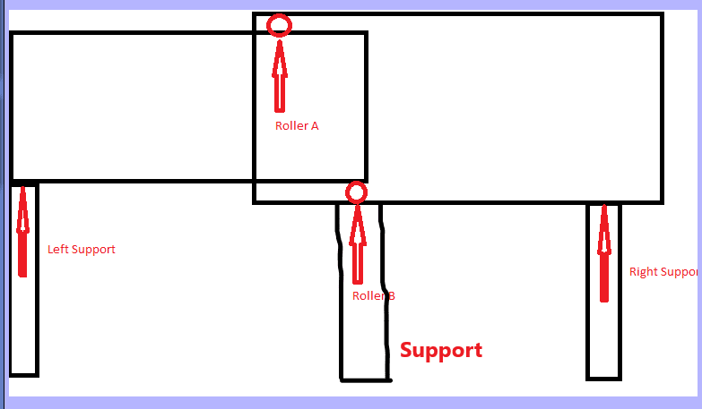
I wanted some clarification for how would the reaction loads at end supports and joint will be calculated in the case shown in the schematic diagram. The load of right structure would be supported by roller A however that load would also be transmitted to roller B. In this for value we can just assume that the uniform distributed load of the structure is 30 kg/m2 and distance horizontal distance between rollers is 1m. Thanks in advance.
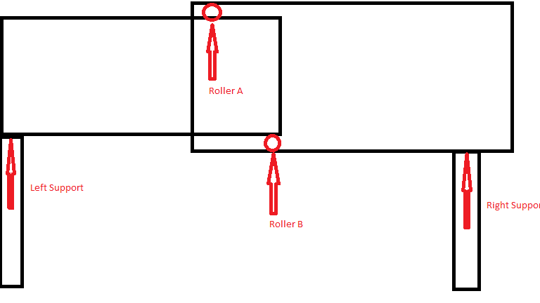
structure_yvzjdh.png
 
Replies continue below

Recommended for you

Hi adjel

Can you explain the problem in more detail if the load is the large rectangle supported be rollers A and B then what does the right support reaction do?


“Do not worry about your problems with mathematics, I assure you mine are far greater.” Albert Einstein
 
Hi desertfox,

Thank you for your reply. Yes, the load is the large rectangular block you see in the figure. There is an inner and outer rectangular block that functions as a telescopic tunnel. So, basically the right support is mobile (for simplicity not shown)and can move to the right and left direction and roller help in the movement. So, the distance also changes between roller A and B as the outer block moves over the inner block.

Hope, this explains what you were looking for.
 
Since there is no moment transferred between the right and left rectangle due to discontinuity in the rectangles, the load at each support will be simply equal to
R (unit = kg) = w(unit = Kg/m) * Catchment length (unit = m)
Catchment length for end supports will be equals to half of the distance between the consecutive support.

Catchment length for interior supports will be equals to the sum of half of the distance between the consecutive support on either sides.
 
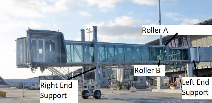
Thank you for your reply @blackstar123. Sorry, I don't understand as what are you mean by consecutive support: for example, if I am talking about the left end support then its consecutive support will be Roller A? Secondly can you explain the last line "Catchment length for interior supports will be equals to the sum of half of the distance between the consecutive support on either sides". Thank you. I am attaching another picture where this structure resembles a boarding bridge and the supports and rollers have been labeled.
adelte1_emkurk.jpg
 
I think the rollers are trapped so they can react load in both directions. Then each element is simply a beam with three simple supports.

another day in paradise, or is paradise one day closer ?
 
This system cannot prevent rotation, thus unstable - no solution.
 
why so … if the rollers can react load in both directions … as they would need to do in the example posted.

moment can be transferred over the roller pair, if one roller load is up and the other down.

another day in paradise, or is paradise one day closer ?
 
The support reactions would be determined the same way whether there are internal rollers or if it were one continuous beam. Globally you have a single beam - as long as the rollers are able to create a force couple to transfer the required moment to resist bending.
 
A couple needs a pair of opposite forces, I don't see it can develop. I think drawing the deflection paths will provide clear view. Note that all points are free to rotate.
 
The couple is formed by the vertical forces at rollers A and B, the distance is the horizontal distance between the two rollers.

It is no different than if you slid one tube inside another tube - this is a very common moment connection for steel utility poles.
 
dauwerda,

I understand that. You can experiment the pipe example at home by place the assembly (loosely fit with overlapping length much shorter than member length) between two tables/chairs without restriction of rotation. If it can stay, I owe you a big one :)
 
adjel,

The structural system in your photo (airport elevated boarding gallery) is similar to the sketch below. Otherwise, the passengers will slide both way toward the center - collapse :) You then can solve the reactions by consistent displacement method, IMO.

e_svu0bd.png
 
retired13 said:
(loosely fit with overlapping length much shorter than member length)
Ah, you just added your own twist to this - obviously you don't want it to be loosely fit. In the situation described and further clarified (by the picture of the jetway) by the OP, it definitely is not loosely fit - the rollers are there to show that it is not loosely fit.
 
retired13 - look back at the jetway photo. There are only two supports. The one thing missing (though mostly irrelevant to the OP's question so long as you know it's there) is the control mechanism that prevents them from sliding out of each other. There's typically a cable system or scissor style mechanism that controls the relative location of the two halves, and prevents them from falling apart. The rollers, installed tight between the two telescoping tubes, resist the internal moment through the force couple. It might help to remove the arrows from the OP's sketch. The actual reactions and load path are slightly more nuanced, and if you walk through it without those you'll probably see it.
 
:) You guys are adding jamming force and introduce shear friction into roller support that make it more looks like continuous...
 
Adjel,
My earlier response was for the beam with rigid internal supports with no continuity between the rectangles. However, this will not the case if your structure is something like the picture you've attached. Your structure will deform as a single unit between two end supports and as others have said, the moment would be resisted due to couple produce at internal contact points between the rectangles.

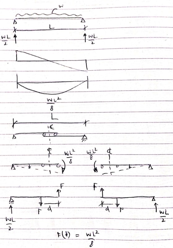
I would analyse this problem as shown below.
Screenshot_20200418_031220_kqo2zq.jpg
 
retired13 said:
You can experiment the pipe example at home by place the assembly (loosely fit with overlapping length much shorter than member length) between two tables/chairs without restriction of rotation. If it can stay, I owe you a big one :)

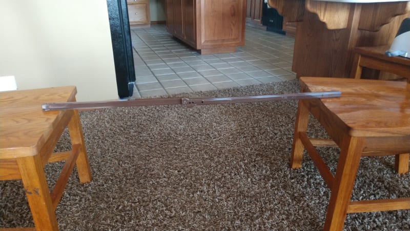
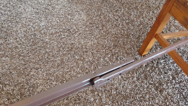
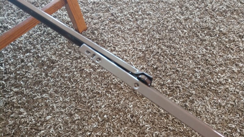
I didn't have any pipe laying around that would fit the bill, but I did have drawer slides, which are a better representation of the OP anyway. As you can see, no sliding or rolling issues:

drawer_slide_1_w2zwe6.jpg

drawer_slide_2_y0ajbt.jpg

drawer_slide_3_vjuaiz.jpg
 
Looks to be a simple statics problem involving two simple span beams. The left hand beam spans from left support to Roller B carrying some uniform load plus a point load at Roller A. The right hand beam spans from Roller A to right support.

At least, that is what I get from the first sketch. Looking at the photo, it's hard to say whether or not that is the correct representation. The diagram by retired13 suggests that Roller B supports the right hand beam.

Adjel needs to clarify. Is the right hand beam supported by Roller B?

Edit: On further inspection of the photo, it appears there is no support between the left and right support. That means that Rollers A and B act in opposite directions with a reaction approximately equal to the moment divided by one meter. The contraption would have a tendency to bind if that is the case. Might be okay with sufficient counterweight beyond the right support.

BA
 
Status
Not open for further replies.

Part and Inventory Search

Sponsor