Continue to Site

Eng-Tips is the largest engineering community on the Internet

Intelligent Work Forums for Engineering Professionals

  • Congratulations KootK on being selected by the Eng-Tips community for having the most helpful posts in the forums last week. Way to Go!

Reaction loads at the Support of an overlapping structure 12

Status
Not open for further replies.

rifa92

Mechanical
Apr 17, 2020
30
Hi,

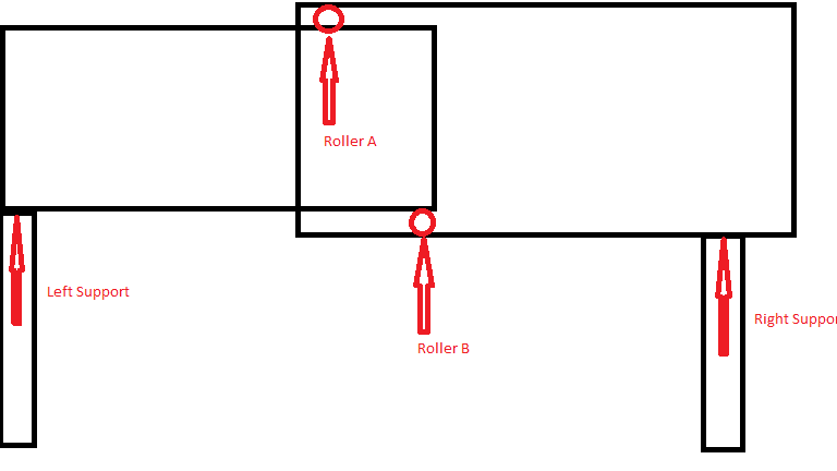
I wanted some clarification for how would the reaction loads at end supports and joint will be calculated in the case shown in the schematic diagram. The load of right structure would be supported by roller A however that load would also be transmitted to roller B. In this for value we can just assume that the uniform distributed load of the structure is 30 kg/m2 and distance horizontal distance between rollers is 1m. Thanks in advance.
structure_yvzjdh.png
 
Replies continue below

Recommended for you

BA's edit very close to my thought.

Applaud to dauwerda's presentation, I need time to think about.
 
I was wrong. The couple will develop, and no rotation will occur.

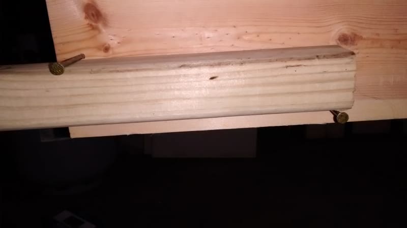
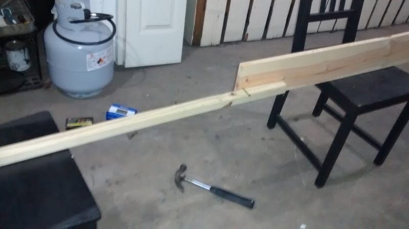
IMG_20200417_191659910_el7c6c.jpg

IMG_20200417_191719260_g4tf3l.jpg
 
Retired, can you make another model with both nail over one another and closer to the edge of both wood pieces.

Do they toppled over then?
 
phamENG, answering your question yes there would be some limiting mechanism limiting switch, cable etc that would prevent the blocks from pulling out.
 
BAretired, yes load of left block is supported by Roller-B. So, that is the tricky part it is like a cycle and understandable practically that Roller B is basically supporting the complete load of left block and point load from Roller A. Similarly, Roller A is supporting the load of the right block but again its own load is also being transmitted to it via Roller B. But how would you actually calculate the loads or design such a structure.

I like Blackstar123 approach by trying to solve it as an indeterminate structure. The maximum deflection is at the center somewhere between Roller A and B as would be in a simply supported beam.
 
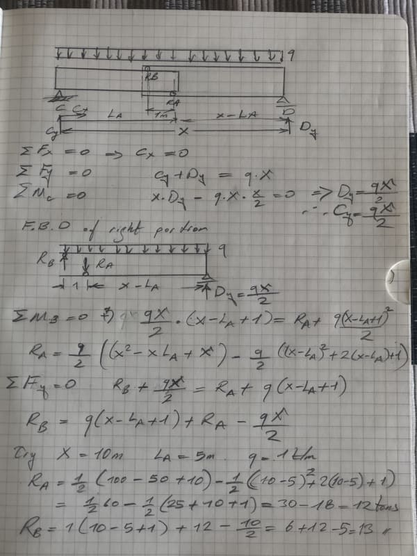
I have seen this thread yesterday and did not reply for thinking a simple determinate static problem..I got nervous due to curfew and tried to solve the problem just for joy..The reactions at Roller A and B are similar with socket foundation. The reactions A and B develop couple but they are not identical..


Telescopic_beam_roller_reactions_IMG_0168_djl7xt.jpg
 
HTURKAK,
Your approach is a good example to understand the statics of the problem. But, why not go for the simplest route? Reactions at contact location could be simply obtained by dividing the moment with the couple arm at the location of break in the beam.

Ra=Rb = M/d=(1x10^2/8)/1 = 12.5 ton (i.e., if the connection is provided at centre of the beam)

It's similar to finding the couple force for a design of moment connection.
 
Dear Blackstar123 ;

If the resisting couple would develop at the same section and they are horizontal couple, your approach is O.K.
In this case , the roller reactions are vertical and at seperate sections. With your approach, (taking the moment at average distance of two rollers, and dividing with couple arm) you will get the average of two forces..May be acceptable but not exact..
 
Blackstar,

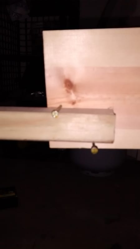
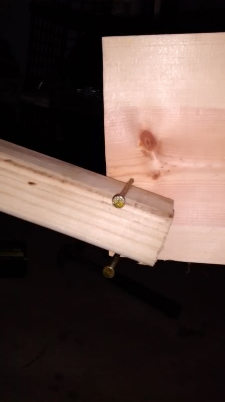
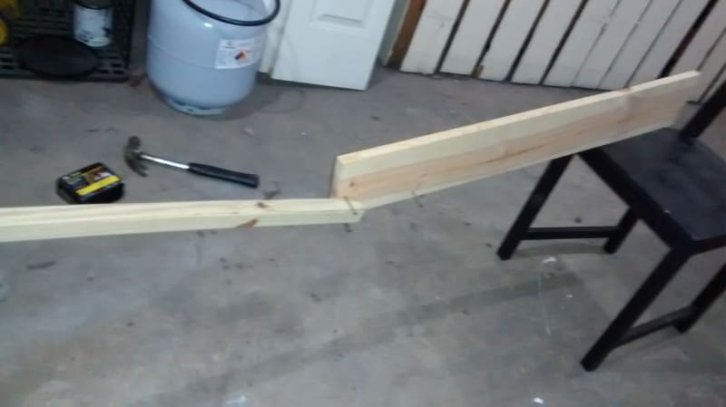
The first photo shows the system is stable when pins are spaced 2"apart. The next two show the deflected shape when pins are vertically aligned, the deflection is large, but collapse is prevented through jamming due to geometry.


IMG_20200418_070421137_q6xsfm.jpg

IMG_20200418_070238644_nwkwfs.jpg

IMG_20200418_070303203_eghw7k.jpg
 
HTURKAK,
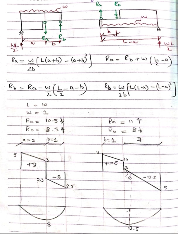
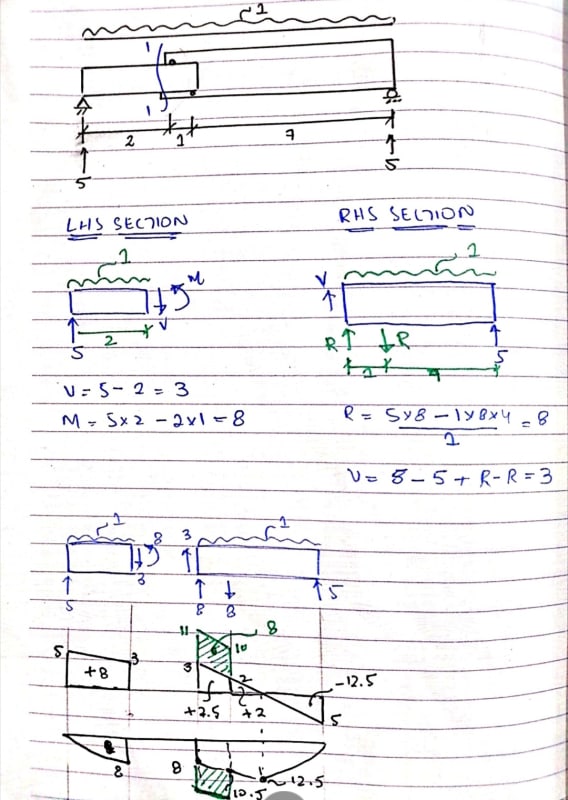
I was trying to solve the problem in the similar technique as yours. This is what I found, Forces Ra and Rb from the LHS and RHS section doesn't matched up, as shown in following calculations.
Screenshot_20200418_172952_jb9b9q.jpg


IMO, the reason for this is that there should be a moment term in equilibrium equation for moments, which we aren't considering.
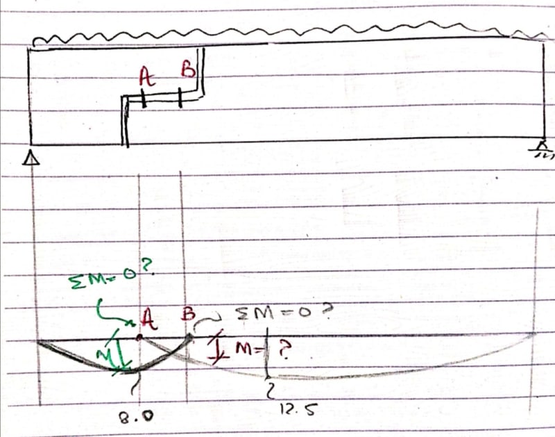
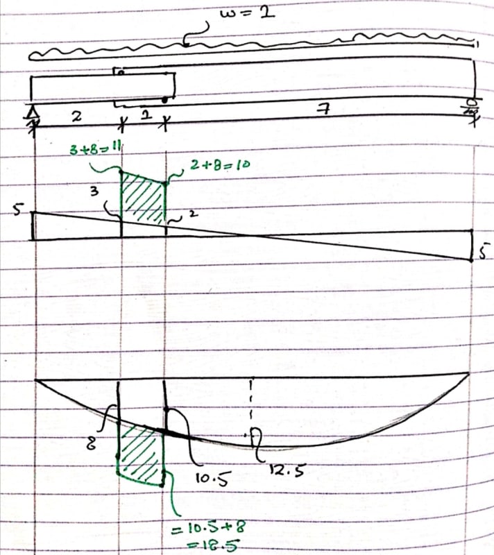
For sum of all moments = 0, we will get combine moment diagram as follows. From this it's clear that the moment at point A and B is not zero as assumed.
Screenshot_20200418_173022_ne4ab7.jpg


Also, does the shape of moment diagram make sense? It doesn't to me.
 
Retired, thank you for sharing the results of your practical experiment.
I wished your wood sticks were a little flexible so that we could see the deformed shape for loaded beam with internal couple case.
 
Blackstar123 - Your sketch double-counts the load on a portion of the beam. I've marked the double-counted portions in blue:

RollerBeam-1-600-Blue_i59ciz.png


Force R[sub]a[/sub] has to be exactly equal and opposite in the LHS and RHS. Same for force R[sub]b[/sub].
Both R[sub]a[/sub] and R[sub]b[/sub] are forces "inside" the beam. When the two parts of the beam are joined, R[sub]a[/sub] and R[sub]b[/sub] do not affect the shear and moment diagrams.

Shear and moment diagrams for the joined beam will be identical to a single member beam. If this was not true, beam end reactions would not be wL/2, which your calcs correctly show.

[idea]
 
BA,

Note that in the original sketch, the two plates overlaps over a distance "b" as indicated in Blackstar's sketch. However, I don't think Blackstar's case is equivalent to the OP's case.

I am trying another solve, but the equations are stretched out as stinky socks ...

Any solution should be tested with the two extreme cases to validate its correctness, b = 0 (no solution), and b = L.
 
Blackstar123 (Civil/Environmental) said:
HTURKAK,
I was trying to solve the problem in the similar technique as yours. This is what I found, Forces Ra and Rb from the LHS and RHS section doesn't matched up, as shown in following calculations.....

Your sketch double counts the load at portion 'b' . Total force is w*L but in your sketch w(L+b)...
 
HTURKAK,

Please see my latest response to BAretired. There is an overlap region in OP's sketch (he has double plates), thus double load. This maybe the only thing you have missed in your calculation.
 
From a safety standpoint, it would be better to convert Roller A and B to Hinge A and B. Then the right hand support could be a roller; after all, it has wheels on the pavement. If there are three rollers, the structure becomes unstable.

The applied load of 30 kg/m represents the weight of the overlapping trusses, so to be precise, there should be an additional 30 kg/m in the overlapping portion. Since the truss extends beyond the right hand support with an operator's cab at the end, there will be a cantilever moment which alters the left hand reaction by M/L and alters the shear and moment diagram for the entire span.

Solving for the hinge reactions is statically determinate but a bit tedious.


BA


retired13 (Civil/Environmental);


For simplicity , i assumed total load ( W ) is uniformly distributed. If we divide the load DL and LL , DL portion will double at overlapping portion , while LL will remain the same..
 
retired13 said:
BA,

Note that in the original sketch, the two plates overlaps over a distance "b" as indicated in Blackstar's sketch. However, I don't think Blackstar's case is equivalent to the OP's case.

I am trying another solve, but the equations are stretched out as stinky socks ...

Any solution should be tested with the two extreme cases to validate its correctness, b = 0 (no solution), and b = L.

I didn't think they should be too stinky, retired13, but I haven't checked below to see if the two sets of equations agree. I will do that next.

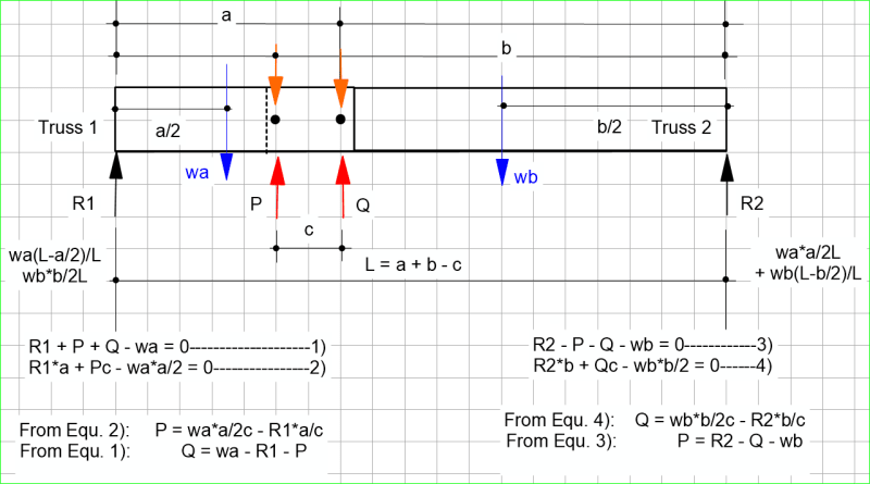
In the sketch below, the two forces P and Q which occur at the hinges (Rollers A & B) are assumed to be in tension, i.e creating an upward force on Truss 1 and a downward force on Truss 2. We know they can't both be tension, but the sign should work out that one is positive and the other negative.

Overlapping_Trusses_ze8cnl.png


EDIT:
Equation 4 above should read R2.b - Qc - wb*b/2 = 0
so Q = R2.b/c - wb.b/2c


BA
 
SlideRuleEra & HTURKAK,
Thank you for pointing out my mistake, this was really driving my crazy. I now realized that I was trying to compare forces for left and right hand side sections with cuts at different locations.

Retired said:
However, I don't think Blackstar's case is equivalent to the OP's case.
I was trying to create a same scenario but for a beam with a somewhat same moment resisting mechanism at the cut point as OP's case. Onwards I'll use OP's originaly posted beam to reduce the confusion.

slideruleera said:
Both Ra and Rb are forces "inside" the beam. When the two parts of the beam are joined, Ra and Rb do not affect the shear and moment diagrams.
That is my understanding too. And, this is what I am trying to prove here that the internal couple at "support/contact points" doesn't affect the internal shear and bending moment and internal couple force could be found by simply dividing the moment with the couple arm.
Anyhow, thanks for seconding this opinion.

I've revised my calculations for the same example. Results looks more reliable now.
Following calculations shows the shear and bending moment for a couple resisting the CCW movement of right part of the beam.
I've shown the shear and bending moment due to internal couple in green, just to clearly show their effect on internal forces. However, there will be an equal and opposite couple (not shown here) acting on the left part of the beam, trying to rotate it CCW. Thus, both couple forces will nullify the effect of each other on the beam and the net shear and bending forces result will be same as for a normal simply supported beam (i.e., shown in black).

Screenshot_20200419_183135_jnciqd.jpg


Results due to couple acting on left part of the beam only. When result due to couple acting on right part is added in the following, green area of the digrams will become zero.
Screenshot_20200419_183223_xkhjpp.jpg
 
BA,

Can you try a numerical case a=4, b=6, c=2, L=8, and see what are the reactions.
I need time to think if the two systems are equal.
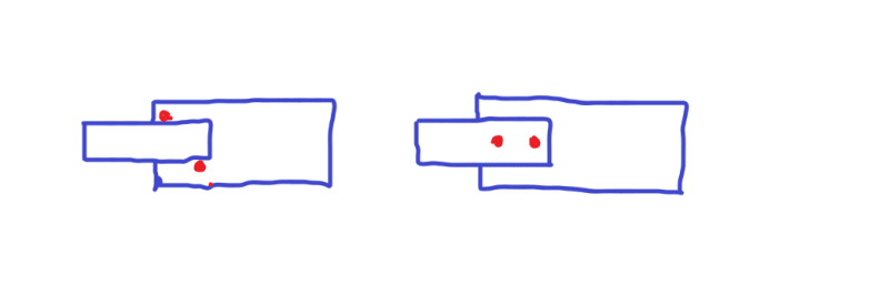
Note that the system on the left, the boards are relying on the pair of rollers to maintain equilibrium; and equilibrium is maintained for the right hand side system, through a pair of pins.

b_sld30x.png
 
Status
Not open for further replies.

Part and Inventory Search

Sponsor